Designing a New Autonomous Layer Between the Ocean Surface and Conventional Flight
Designed by: Skills Gap Trainer
A first-principles architecture for a compact maritime vehicle that can float, rise onto hydrofoils, enter ground-effect flight, return safely to the water, and mature through disciplined product cycles
The objective is not to make a boat fly at any cost. It is to design the lightest useful maritime vehicle that can repeatedly float, foil, fly, return to the sea, and survive the transition between those states.
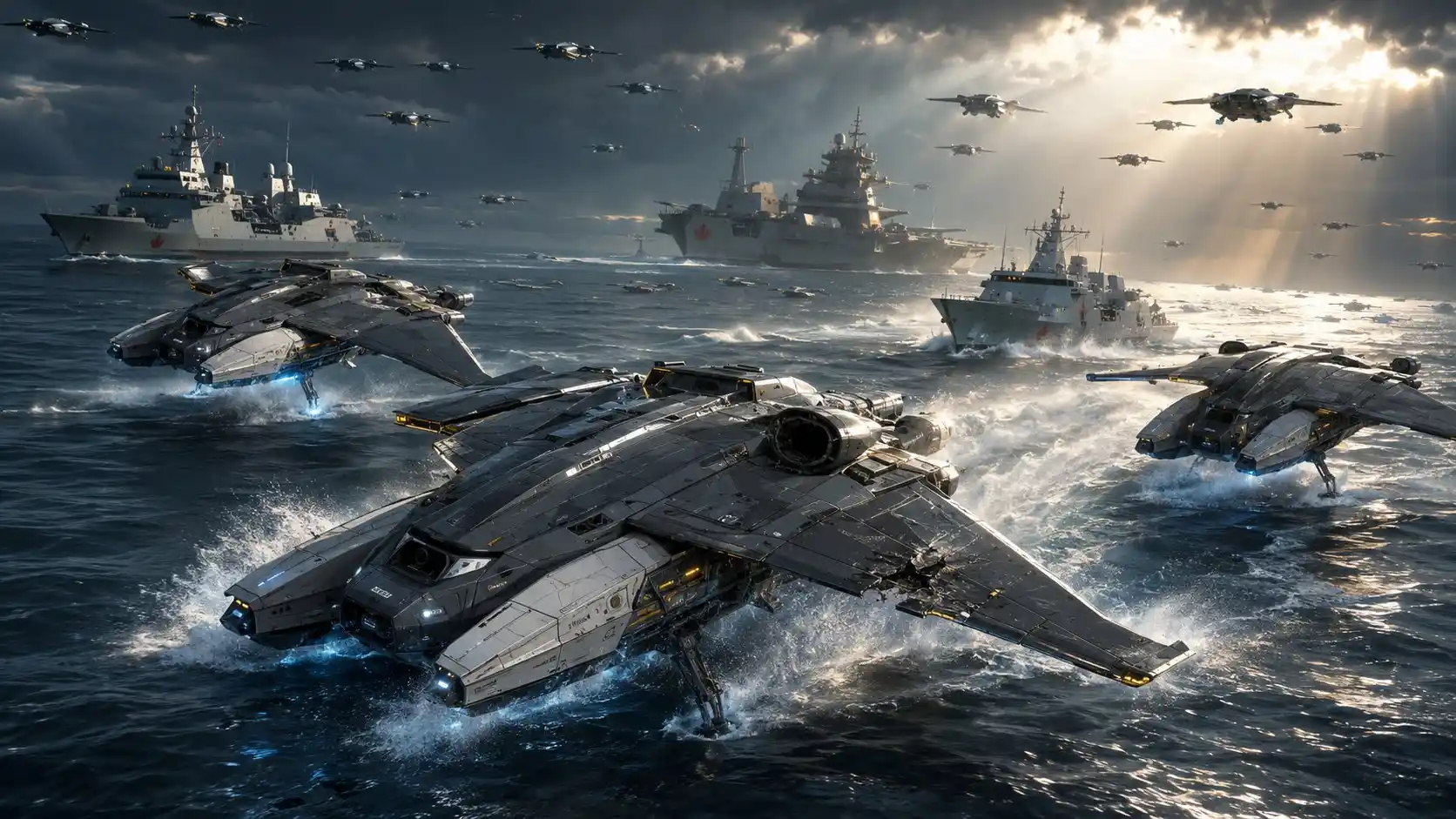
“The fleet waits on the ocean. The wings open. The vessels accelerate onto their foils. The sea releases them. The navy becomes the sky fleet”
– Valentin at SGT, Founding Engineering Flag Officer https://x.com/SkillsGapTrain/status/2078043412562063581
Design-status legend
Every important claim in this article belongs to one of five categories.
Established principle A physical or engineering relationship accepted independently of X-Wing.
Existing precedent A capability, standard, research result, or vehicle class that already exists outside this project.
Derived architectural recommendation A design choice inferred from the governing physics and systems trade space.
Provisional design envelope A preliminary value chosen to guide visualization, simulation, and early parametric analysis. It is not a demonstrated specification.
Unknown pending analysis or testing A question that cannot be answered honestly through writing or rendering alone.
This distinction is essential. A coherent architecture is not the same thing as a tested vehicle, and a compelling technical image is not the same thing as a validated engineering drawing.
Executive summary
X-Wing V2 is a compact autonomous aerospace-maritime vehicle designed to operate in the physical layer between a conventional unmanned surface vessel and a conventional aircraft.
It can remain on the water in a low-energy persistence state. When rapid relocation becomes useful, its outer wings deploy, active hydrofoils raise most of its marine structure clear of the water, and aerodynamic lift gradually assumes the vehicle’s weight. X-Wing then flies immediately above the sea in ground effect before returning to maritime operation.
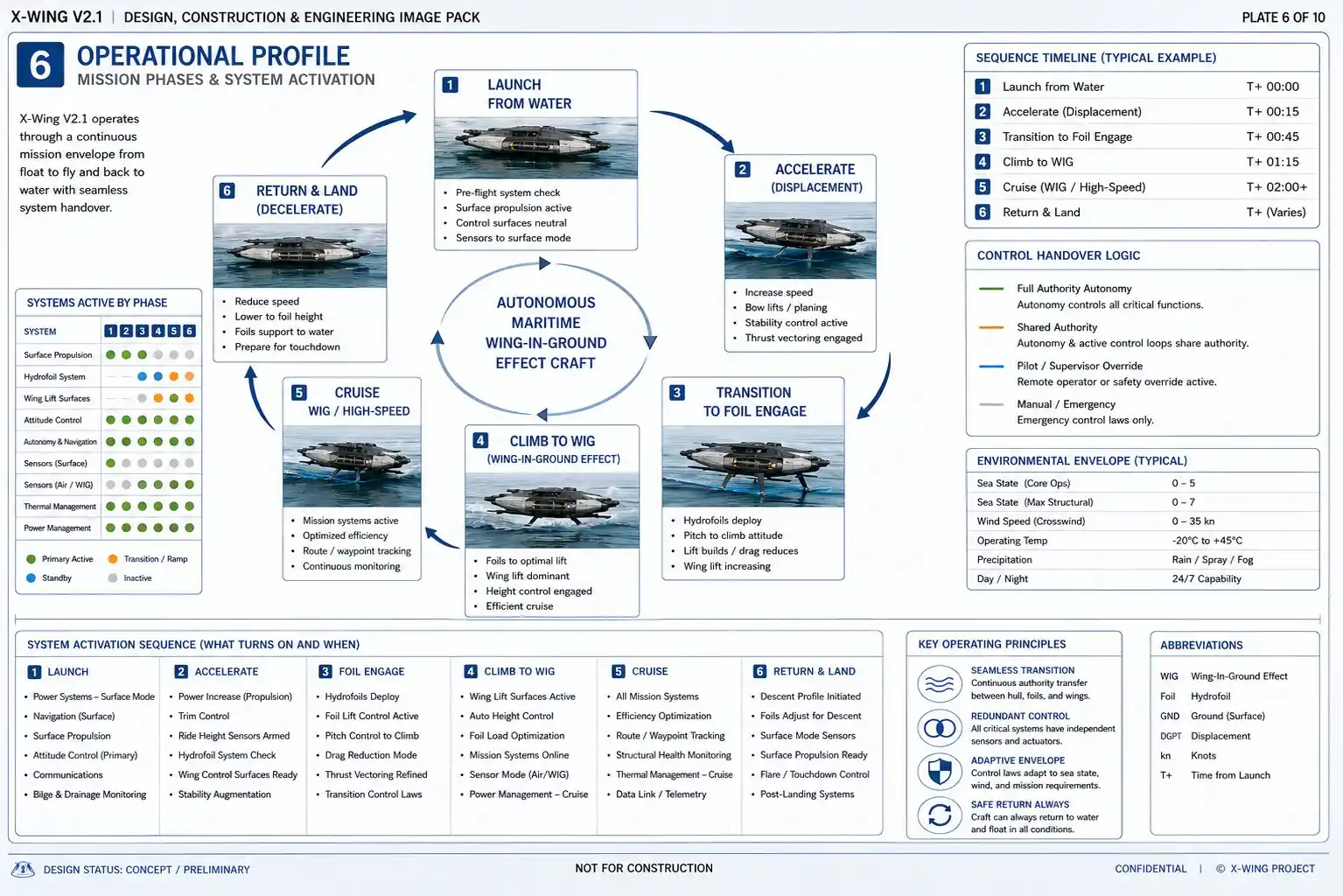
The operating sequence is:
Float → foil → fly → return → recover → repeat
The concept does not yet depend on a flying destroyer, a supersonic boat, or an invisible machine. It begins at the individual-vehicle scale, approximately within the dimensional class of a fishing boat or small patrol craft. That is the level at which the difficult questions can be answered through affordable product cycles.
X-Wing is defined as a maritime-regime wing-in-ground-effect craft whose normal flight mode remains close to the water. The International Maritime Organization recognizes WIG craft as vehicles supported in their principal operating mode by aerodynamic forces while flying at low altitude above the sea but out of direct surface contact. IMO guidance treats their design as a combined maritime and aviation problem rather than as an ordinary ship or ordinary aircraft problem.
The strongest V2 architecture uses:
- A broad, fixed aerodynamic lifting centrebody
- Two swept outer wing panels folding rearward and inward
- Two narrow, replaceable flotation sponsons
- A provisional four-cassette active hydrofoil system
- Four fixed aft-facing pusher propulsors
- Elevons, centrebody flaps, differential thrust, and active foil control
- A hybrid damage-tolerant composite structure
- Predictive wave-field sensing
- Deterministic safety control beneath higher-level autonomy
- A standardized internal mission bay
- Replaceable marine-impact and propulsion modules
- Layered signature management without claims of invisibility
The vehicle’s greatest technical challenge is not ordinary surface travel or ordinary flight. It is the transfer of support and control among three regimes:
- Buoyancy while hull-borne
- Hydrodynamic lift while foil-borne
- Aerodynamic lift while flying in ground effect
The program should therefore mature through six product cycles:
- Simulation and subscale evidence
- Autonomous surface operation
- Autonomous hydrofoil operation
- Fixed-wing ground-effect flight
- Folding-wing ground-effect flight
- Modular operational configuration
The article’s current overall architectural score is 9.5/10. That is approximately the highest honest score available before computational analysis and physical testing. Demonstrated vehicle capability remains not yet scoreable.
Introduction — A machine waiting on the water
X-Wing waits quietly on the ocean.
Its two outer wing panels are folded rearward and inward along the upper centrebody. They do not hang beside the craft like improvised appendages, nor do they overlap in an unstable pile above it. They become part of a compact maritime configuration while preserving the identity of the underlying lifting body.
Two narrow flotation sponsons carry the vehicle’s weight. They keep the expensive aerospace structure above the most persistent water impacts and provide enough lateral separation for stable surface operation. The propulsion system can remain inactive or operate at low power. X-Wing does not need to generate aerodynamic lift merely to remain present.
In this condition, the ocean performs the work.
The vehicle can wait, move slowly, hold position, conduct system checks, collect information, support communications, transport a modular payload, or return home after an interrupted mission. Unlike an aircraft, it is not committed to consuming energy continuously just to avoid falling.
Then the operating requirement changes.
The outer panels deploy and align with the fixed centre wing. Structural locking wedges and pins close the flight-load paths. The vehicle accelerates on the water, but it does not attempt to force its complete hull structure to extreme speed. Active hydrofoils begin carrying the load and raise most of the sponsons clear of direct contact.
Wetted area falls. Slamming loads decrease. The craft continues accelerating while aerodynamic lift grows across the centrebody and deployed outer panels.
Eventually the hydrofoils unload.
X-Wing is no longer travelling through the water. It is flying immediately above it.
The craft remains below the normal operating layer of conventional aircraft and within the environment that shaped its architecture. It uses ground effect to reduce some of the aerodynamic penalties associated with producing lift, but it also accepts the difficult control problem created by flying above a moving surface.
Later, X-Wing returns to the sea.
That is the essential idea: the vehicle does not choose permanently between being a ship and being an aircraft. It changes which physical system carries its weight according to the mission phase.
The individual technologies are not imaginary. Hydrofoils, folding wings, composite structures, distributed electric propulsion, autonomous vessels, and WIG craft all exist as separate engineering domains. NASA ground-effect research has demonstrated that wing geometry, aspect ratio, angle of attack, and height above the surface materially affect lift, drag, and height stability.
The engineering question is whether these domains can be integrated without allowing their penalties to compound faster than their advantages.
- Can the wings fold without creating an intolerably heavy root structure?
- Can the hydrofoils lift the vehicle through the highest-drag region without producing unstable pitch behaviour?
- Can propulsion remain protected from spray while preserving efficient airflow?
- Can the autonomous controller predict the ocean ahead rather than reacting too late?
- Can the structure withstand both aerodynamic bending and repeated water impact?
- Can the craft be repaired without treating the entire vehicle as disposable?
- Can it complete the full transition thousands of times rather than once?
X-Wing V2 is the architecture derived from those questions.
X-Wing Master Geometry and Dimensions
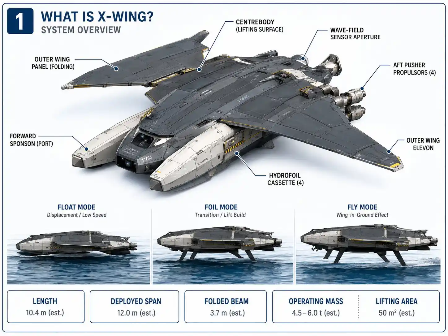
Caption: Preliminary X-Wing V2 geometry reference. Dimensions shown are design-control ranges for visualization and early parametric study, not validated production specifications.
Part I — Finding the correct problem
1. The missing operating layer
Conventional autonomous surface vessels and aircraft possess almost opposite strengths.
A surface vehicle can persist economically because buoyancy supports its weight. It can carry dense equipment, interact naturally with maritime infrastructure, and remain recoverable even when propulsion is unavailable. Its limitation is speed. Water is dense, and hydrodynamic resistance, wave-making, slamming, and spray become severe as velocity rises.
An aircraft avoids most of that hydrodynamic resistance once airborne. It can relocate rapidly and cross irregular surface conditions. But flight requires continuous aerodynamic support, and aircraft generally depend on different launch, recovery, maintenance, regulatory, and operating systems.
X-Wing occupies the space between them.
It is designed around three principal support modes:
Float
The sponsons displace water and carry the vehicle through buoyancy. Surface operation emphasizes endurance, recoverability, low-speed navigation, and energy conservation.
Foil
Hydrofoils generate hydrodynamic lift and raise most of the sponsons clear of the water. This reduces wetted area and provides a controlled bridge between hull-borne operation and flight.
Fly
The centrebody and deployed wing panels generate aerodynamic lift. The vehicle operates in ground effect above the water without direct surface contact.
This leads to the first defining principle of the project:
X-Wing is not primarily a faster boat or a lower-flying aircraft. It is a vehicle designed to change its dominant source of support.
2. Why the first vehicle must remain small
The project initially considered the possibility of scaling the idea toward major surface-combatant dimensions. First-principles analysis shows why that should not be the starting objective.
Mass does not scale harmlessly.
As vehicle dimensions and weight grow, aerodynamic lifting area, structural bending moments, hinge loads, impact forces, propulsion power, manufacturing complexity, and cost all increase. A large vehicle may eventually become possible, but it would need to evolve through many aerospace product cycles rather than emerge as a conventional ship with attached wings.
The correct first step is the smallest vehicle large enough to produce representative evidence.
That vehicle can answer:
- Can hull-borne operation transition smoothly to active hydrofoil support?
- Can the hydrofoils maintain control while the wings begin carrying substantial load?
- Can the craft enter ground effect without unstable pitch or height behaviour?
- Can the wings repeatedly deploy and structurally lock after saltwater exposure?
- Can the vehicle land safely after a propulsion or sensor fault?
- Can the sponsons and foils be replaced without rebuilding the centrebody?
- Can autonomous control reject unsafe takeoff conditions?
- Can the complete cycle be repeated economically?
The first objective is therefore not maximum payload, range, or speed.
The first objective is repeatable transformation.
3. What X-Wing is — and what it is not
X-Wing is:
- An autonomous aerospace-maritime platform
- A persistent surface vehicle capable of temporary ground-effect flight
- A hydrofoil-assisted transition craft
- A vehicle optimized for very-low maritime movement
- A modular platform whose airframe is independent of any single payload
- A product architecture intended to improve through measured development cycles
X-Wing is not:
- A conventional fishing boat with wings
- An ordinary aircraft with pontoons added afterward
- A flying destroyer (yet)
- A supersonic watercraft
- An invisible vehicle
- A replacement for conventional aircraft
- A finished weapons platform
- A production-ready system with verified performance
These exclusions are not a retreat from ambition. They protect the design from incoherence.
Part II — The five governing first principles
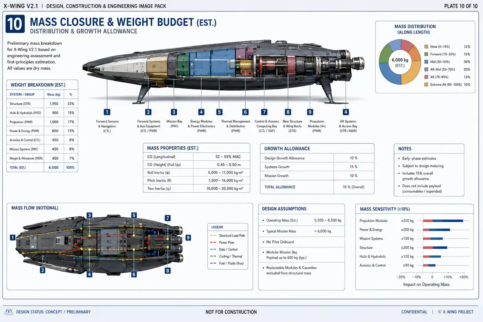
4. First principle: every kilogram must be supported
Everything placed aboard X-Wing must eventually be carried by buoyancy, hydrofoil lift, or aerodynamic lift.
- There is no free hinge.
- There is no free actuator.
- There is no free sensor, battery, generator, cooling system, mission module, structural fitting, or safety reserve.
During aerodynamic flight, the governing relationship is:
L = ½ρV²SCL
Where:
- L is lift
- ρ is air densityV is velocity
- S is effective lifting area
- CL is lift coefficient
The equation does not design the vehicle by itself, but it establishes the trade space.
Increasing velocity increases lift rapidly, but it also increases dynamic pressure, structural loading, control sensitivity, and required propulsion power. Increasing wing area may lower liftoff speed, but it adds structure and complicates folding. Increasing lift coefficient can help only within the constraints of drag, stability, flow separation, and control margin.
- The program must therefore protect separate mass budgets for:
- Primary aerospace structure
- Marine structure
- Wing folding and locks
- Hydrofoil system
- Propulsion
- Energy or fuel
- Flight-control electronics
- Sensors and communications
- Thermal management
- Mission bay
- Design-growth reserve
A design that allocates all mass before detailed analysis has no room to survive reality.
Design implication: X-Wing must become mass-disciplined before it becomes feature-rich.
5. Second principle: water contact is the main transition barrier
Water gives X-Wing persistence, but it opposes acceleration.
A hull moving through the ocean experiences skin friction, wave-making resistance, spray drag, ventilation, and impact loading. As speed increases, simply adding more propulsion becomes an inefficient answer because the structure must also become stronger and heavier.
X-Wing therefore should not attempt to reach flight speed as a conventional planing craft.
The hydrofoils exist to escape that trap.
As the foils generate lift:
- Hull immersion decreases
- Wetted area falls
- Wave impacts diminish
- Spray can be controlled more effectively
- Aerodynamic lift can assume the load gradually
The transition should occur as a controlled exchange rather than a dramatic leap.
Design implication: unload the hull as early and cleanly as practical.
6. Third principle: the ocean is a moving runway
X-Wing does not fly above a fixed plane.
The water surface rises, falls, slopes, breaks, and moves. Long swells may carry smaller wind-driven waves. A safe corridor can change within seconds.
This transforms altitude control into a predictive surface-estimation problem.
A downward-looking sensor tells the vehicle where the water is now. At high speed, that is insufficient. The craft must estimate where the water will be when it arrives.
Its controller must understand:
- Wave height
- Wave period
- Wave direction
- Crest velocity
- Local slope
- Cross-sea interactions
- Spray and visibility confidence
- Available landing corridor
Historic NASA testing found that low-aspect-ratio wings in ground effect could exhibit height stability at positive angles of attack and instability under other conditions, reinforcing the need to validate stability throughout the full height, speed, pitch, and centre-of-gravity envelope.
Design implication: forward wave-field prediction is flight-critical.
7. Fourth principle: transformation mechanisms impose penalties
The folding wings are valuable because they reduce surface beam and protect the deployed span from unnecessary exposure. They are also one of the most dangerous sources of mass and complexity.
Each fold requires:
- A hinge
- Local reinforcement
- One or more actuators
- Wiring or fluid transfer
- Alignment hardware
- Position sensing
- Structural locks
- Seals
- Drainage
- Inspection access
- Emergency recovery provisions
The correct architecture minimizes the amount of wing that moves.
X-Wing therefore retains a permanent central lifting body and folds only the outer panels.
The mechanism must separate deployment from structural support:
- Actuators move the panels
- Hinges guide them
- Alignment fittings position the spars
- Structural wedges and pins close the load path
- Bulkheads and spar fittings carry the flight loads
Design implication: the actuator deploys the wing; the locked structure carries the vehicle.
8. Fifth principle: survivability comes from compounding advantages
No practical material or shape makes X-Wing invisible.
Composite construction may reduce weight and support signature management, but the vehicle still contains electrical conductors, metallic joints, propulsors, heat sources, cooling openings, sensors, and communications equipment.
Very-low flight may exploit radar-horizon geometry and complex reflections near the ocean, but modern surveillance systems are designed to detect small objects in clutter.
Spray may conceal the craft under some visual conditions, but a large white plume can also reveal its position.
The truthful objective is not invisibility.
It is to reduce the time and confidence available to any observer attempting to detect, classify, and continuously track the craft.
That can emerge from:
- Small dimensions
- Clean external geometry
- Low-altitude operation
- Controlled heat distribution
- Quiet low-speed surface movement
- Reduced wake
- Clean transition with limited spray
- Disciplined transmissions
- Short flight exposure
- Return to the surface when speed is unnecessary
Design implication: pursue layered signature management, not a single stealth claim.
Part III — The provisional V2 design envelope
The following values are provisional design-study ranges. They are intended to make the concept measurable and to guide CAD, mass modelling, CFD, and technical visualization.
They are not achieved specifications.
Geometry
- Overall length: 10.2–10.8 metres
- Deployed wingspan: 11.5–12.5 metres
- Folded beam: 3.5–3.8 metres
- Effective lifting area: 48–55 square metres
- Surface height: approximately 2.0–2.3 metres
- Twin sponsons extending across most of the centrebody length
- Four aft-facing propulsors in fixed symmetrical positions
Mass
- Preliminary maximum operating mass study range: 4.5–6.0 tonnes
- Preliminary wing-loading study range: approximately 85–125 kilograms per square metre
- Empty mass target: low enough to preserve meaningful energy, mission, and design reserve
- Exact mass distribution: unknown pending parametric modelling
Performance study ranges
- Hull-borne persistence speed: approximately 15–40 kilometres per hour
- Hydrofoil transition region: approximately 55–95 kilometres per hour
- Aerodynamic liftoff study region: approximately 105–140 kilometres per hour
- Ground-effect cruise study region: approximately 200–280 kilometres per hour
- Initial height corridor: approximately 0.2–0.5 wingspan above the predicted local wave surface
Power study ranges
- Efficient ground-effect cruise: approximately 0.2–0.5 megawatts
- Short-duration transition power: potentially approximately 0.8–1.5 megawatts
- Final propulsion power: unknown pending aerodynamic and hydrodynamic analysis
These values define a starting search region. They do not define the final vehicle.
The program should maintain separate terms for:
- Minimum foil-borne speed
- Minimum normal ground-effect speed
- Normal cruise speed
- Maximum approved speed
- Maximum safe speed
- Landing-speed range
- Verified sea-state limit
IMO WIG guidance similarly distinguishes operating modes and speed or condition boundaries rather than reducing craft capability to one headline number.
Part IV — The optimized canonical architecture
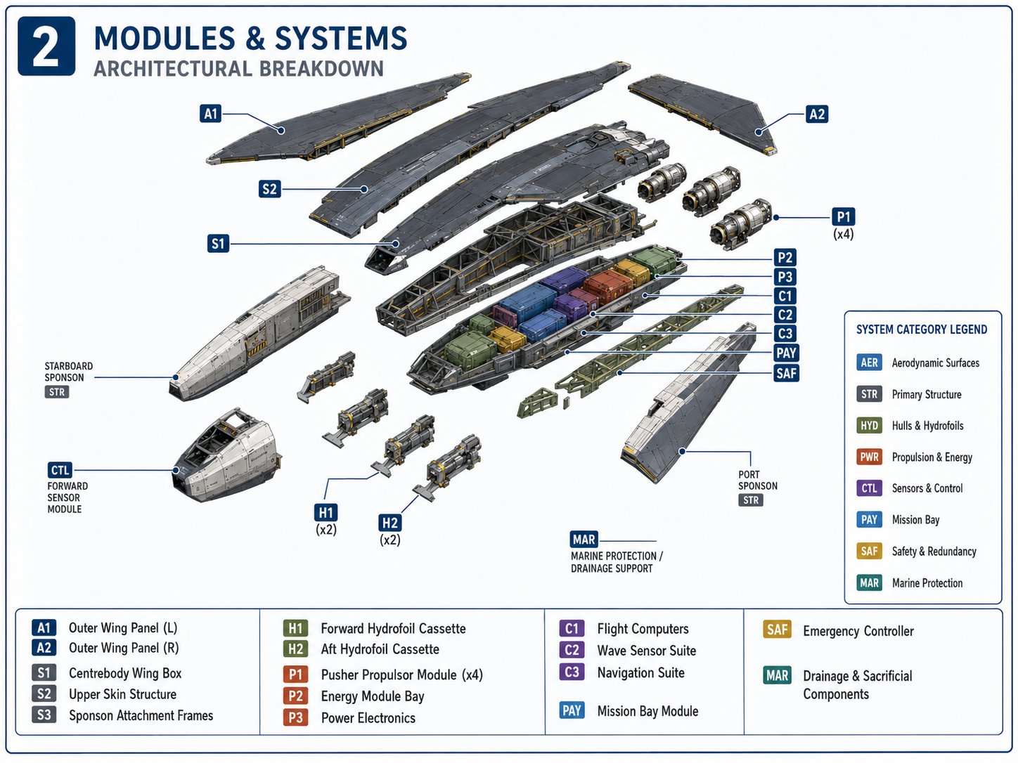
9. A broad aerospace-first centrebody
The primary body must already function as an aerodynamic lifting surface.
It should not be a boat hull waiting for wings to rescue it.
The centrebody provides:
- A substantial share of total lift
- Continuous forward and rear spars
- A deep torsion box
- Internal protected volume
- Root-locking bulkheads
- Sponson attachment frames
- Hydrofoil load-transfer structure
- Propulsor support structure
- Energy, cooling, control, and mission space
This integration improves mass efficiency because the same structure performs several compatible tasks.
The centrebody is simultaneously:
- The fixed central wing
- The main structural beam
- The equipment enclosure
- The bridge between the sponsons
- The foundation of the folded surface configuration
The outer wings enlarge an already functional aerospace form.
10. Twin replaceable flotation sponsons
Two narrow sponsons provide buoyancy and surface stability.
They should remain visually and structurally subordinate to the lifting centrebody. If they become large commercial-style pontoons, the architecture becomes boat-dominant and mass grows rapidly.
Their functions include:
- Reserve buoyancy
- Wide lateral flotation support
- Low-speed surface tracking
- Spray control
- Hydrofoil cassette attachment
- Water-impact absorption
- Towing and recovery interfaces
The most exposed portions should be replaceable:
- Bow impact modules
- Lower shells
- Spray rails
- Hydrofoil leading edges
- Drainage and inspection panels
The centrebody should survive while the marine-contact parts absorb wear.
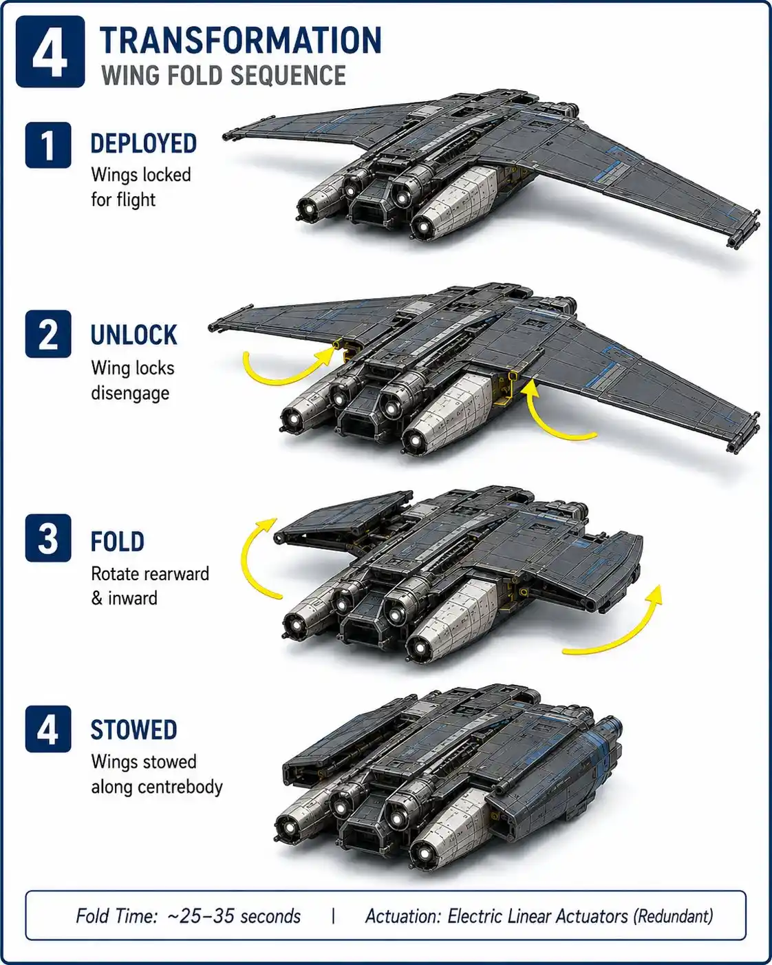
11. Swept folding outer wings
The two swept outer panels fold rearward and inward over the left and right sides of the upper centrebody.
- They do not overlap.
- They do not rotate into the propulsors.
- Their elevons remain clear throughout the motion.
Once deployed, the panels align with the centrebody spars and engage full-depth locking structure.
The folded panels become part of the maritime shell, but they remain identifiable as flight surfaces. The transformation should appear mechanically inevitable rather than magical.
The wing system includes:
- Root hinge axes
- Electromechanical or electrohydraulic actuators
- Alignment cones or tapered fittings
- Structural wedges
- Locking pins
- Position sensors
- Drainage paths
- Sealed control interfaces
- Manual or alternative recovery access
Flight is prohibited unless every primary lock is physically and electronically confirmed.
12. Four integrated aft-facing propulsors
The preliminary V1 design used elevated ring-like propulsors. V2 replaces that arrangement with four aft-facing pusher units integrated along the rear centrebody and inner trailing-wing region.
This improves:
- Spray protection
- Wing-fold clearance
- hrust-line consistency
- Structural load transfer
- Reduced pylon drag
- Differential-thrust authority
- Visual and mechanical coherence
The exact propulsor type remains open.
Potential candidates include:
- Open electric propellers
- Partially shrouded propellers
- Optimized ducted fans
- Hybrid-electric pusher systems
The first demonstrator may use battery-electric propulsion because it simplifies control, instrumentation, and maintenance. That does not imply that batteries will provide the best operational endurance.
The final power system must follow measured requirements.
13. Provisional four-cassette transition foils
The V2 visualization baseline uses one forward and one aft foil cassette under each sponson.
This provides:
- Independent pitch and roll authority
- Symmetrical load distribution
- Modular replacement
- Clear control logic for the first demonstrator
It also adds:
- Four actuators or incidence-control mechanisms
- Four structural attachment zones
- More wiring and sensing
- More opportunities for ventilation, impact, or failure
The program must therefore compare:
- Two-main-foil arrangements
- Three-foil arrangements
- Four-cassette arrangements
The current four-cassette system is a provisional demonstrator architecture, not a declared optimum.
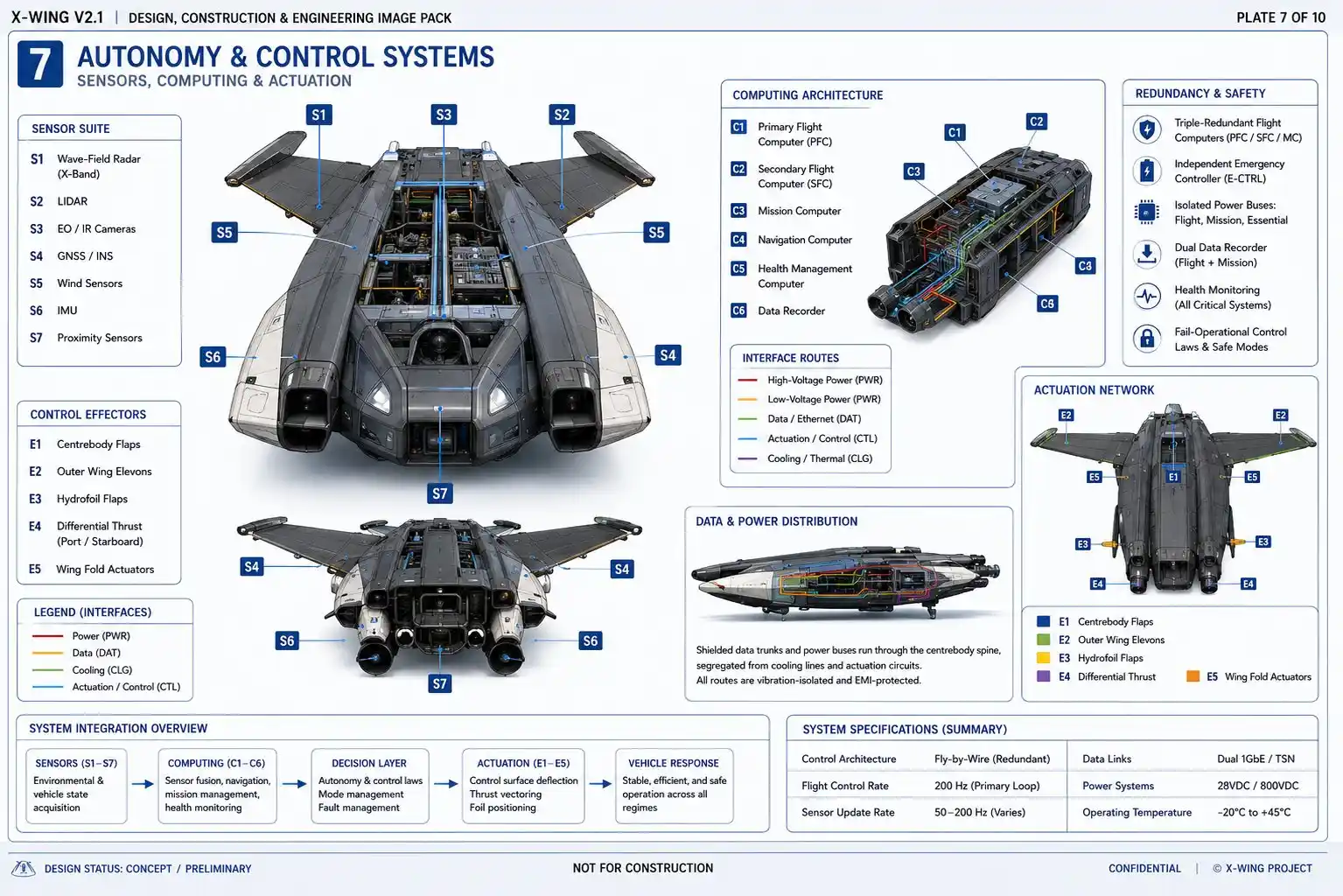
Complete Internal Cutaway Architecture
Part V — Control through three physical regimes
14. Surface control
At low speed, aerodynamic surfaces have little authority.
X-Wing therefore relies on:
- Differential propulsor thrust
- Hydrodynamic steering where required
- Controlled propulsion reversal or vectoring, if selected
- Autonomous low-speed collision avoidance
Surface mode emphasizes persistence, not speed.
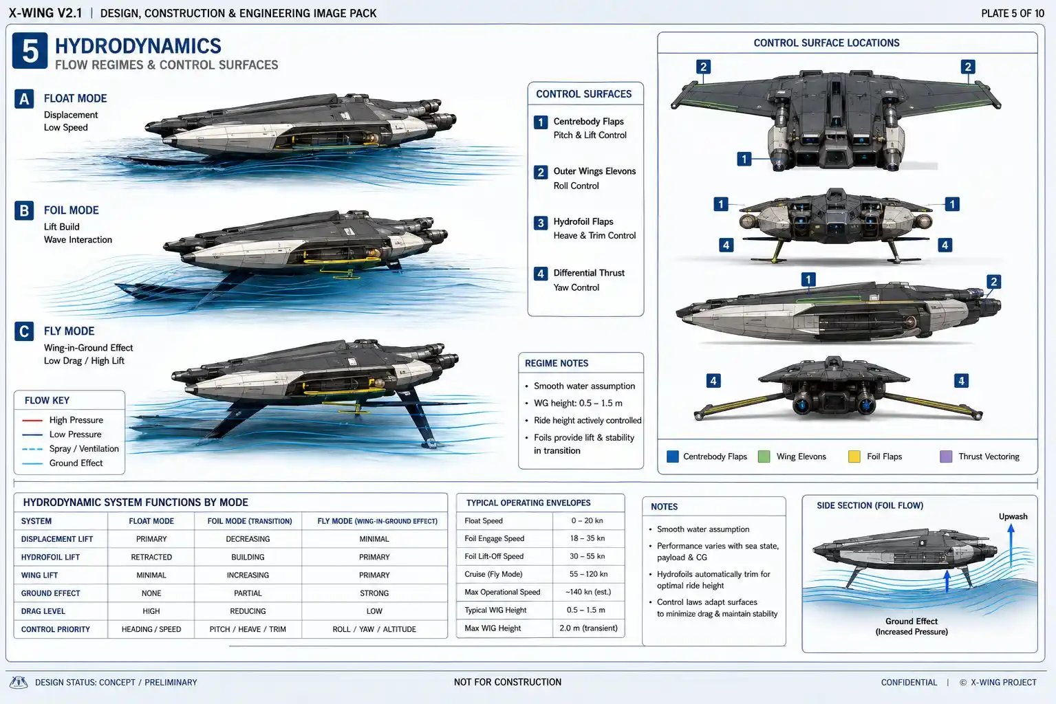
15. Foil-borne control
During transition, the active foils contribute to:
- Pitch
- Roll
- Ride height
- Wave-response damping
- Controlled reduction of hull immersion
The vehicle may simultaneously depend on:
- Residual buoyancy
- Hydrofoil lift
- Growing aerodynamic lift
- Differential thrust
The controller must blend these without abrupt handoffs.
16. Aerodynamic control
In flight, X-Wing uses:
- Outer-panel elevons for pitch and roll
- Centrebody flaps for lift and trim
- Split-drag or compact yaw surfaces if required
- Differential propulsor thrust
- Active height and pitch control
The vehicle’s ground-effect controller must regulate not only attitude but clearance relative to the predicted moving wave surface.
17. Four-layer autonomy architecture
Layer 1 — Hard real-time stability control
Controls:
- Propulsor output
- Elevons
- Centrebody flaps
- Hydrofoil incidence or control surfaces
- Pitch, roll, yaw, and height
Layer 2 — Vehicle-envelope protection
Prevents:
- Takeoff with unlocked wings
- Flight outside structural limits
- Transition in waves beyond the verified envelope
- Operation with an unsafe centre of gravity
- Flight without sufficient sensor agreement
- Operation outside approved height or speed corridors
Layer 3 — Predictive maritime control
Estimates:
- Future wave surface
- Crest position
- Wave direction and period
- Spray and visibility confidence
- Collision corridor
- Safe landing corridor
Layer 4 — Higher mission autonomy
Manages:
- Route planning
- Energy allocation
- Communications timing
- Fleet coordination
- Mission-module operation
- Recovery selection
Higher autonomy may request a manoeuvre. It cannot override the safety controller.
DNV’s AROS framework likewise divides autonomous and remotely operated vessel assurance across navigation, engineering, operational, and safety functions, while distinguishing levels and locations of control.
Folding Wing, Hinge, and Structural Locks
Naval Hydrodynamics and Hydrofoil System
Part VI — Propulsion, energy, and thermal architecture
18. Propulsion requirements
The system must provide two very different power profiles.
Transition requires high short-duration power to overcome hydrodynamic drag, accelerate the foil-borne vehicle, and establish aerodynamic lift.
Ground-effect cruise may require substantially less power once the vehicle is aerodynamically supported and operating near its efficient condition.
The propulsion system must therefore support:
- High transient power
- Efficient continuous cruise
- Fine differential control
- Low-speed surface manoeuvring
- Continued operation after loss of one unit
- Protection from saltwater and spray
- Rapid module replacement
19. Demonstrator energy system
Early product cycles should prioritize test simplicity.
A battery-electric demonstrator offers:
- Precise control
- Immediate torque response
- Simpler instrumentation
- Fewer moving power-generation components
- Easier module replacement
Its disadvantages include:
- High energy mass
- Limited endurance
- Thermal-management demands
- Potentially long charging or turnaround time
Those disadvantages are acceptable if the purpose of the first vehicle is to prove transition and control rather than operational range.
20. Operational energy trade
Later cycles may compare:
- Improved battery-electric systems
- Hybrid-electric generation
- Turbogenerator systems
- Separate surface and flight power arrangements
- Alternative fuels or energy carriers
No energy technology should be selected because it sounds advanced. It must win against measured mass, endurance, cooling, acoustic, maintenance, and safety requirements.
21. Thermal management
Heat cannot disappear.
The vehicle must control:
- Battery or generator heat
- Motor heat
- Power-electronics heat
- Flight-computer heat
- Sensor heat
- Environmental solar loading
Cooling architecture may include:
- Internal liquid loops
- Distributed heat-spreading structure
- Protected air intakes
- Controlled outlets
- Heat exchangers isolated from direct spray
- Emergency thermal derating
Thermal control affects both reliability and external signature.
Propulsion, Energy, Cooling, and Electrical Architecture
Part VII — The moving ocean and predictive control
22. Building a future wave map
The controller should create a three-dimensional prediction of the surface ahead.
Potential sensing inputs include:
- Forward marine radar
- Optical stereo cameras
- LiDAR where conditions permit
- Radar or laser altitude measurement
- Inertial navigation
- Air-data systems
- Satellite navigation when reliable
- Structural-load measurements
- Foil-state and propulsor feedback
The system must also estimate confidence.
A wave map with low confidence should not be treated as a precise surface.
The controller should decide whether to:
- Continue takeoff
- Delay takeoff
- Change heading
- Increase clearance
- Reduce speed
- Land
- Remain on the water
A mature autonomous system is defined partly by what it refuses to do.
23. Safe flight corridor
X-Wing does not maintain one fixed height above mean sea level.
It maintains a dynamic corridor above the predicted local wave surface.
The corridor depends on:
- Wingspan
- Speed
- Wave amplitude
- Wave period
- Pitch and height stability
- Sensor confidence
- Landing options
- Obstacle clearance
The lowest possible altitude is not automatically the best altitude.
The best altitude is the lowest one that preserves reliable control, sufficient margin, and a safe return path.
Predictive Wave-Following and Flight Control
Part VIII — Structure, naval loads, and materials
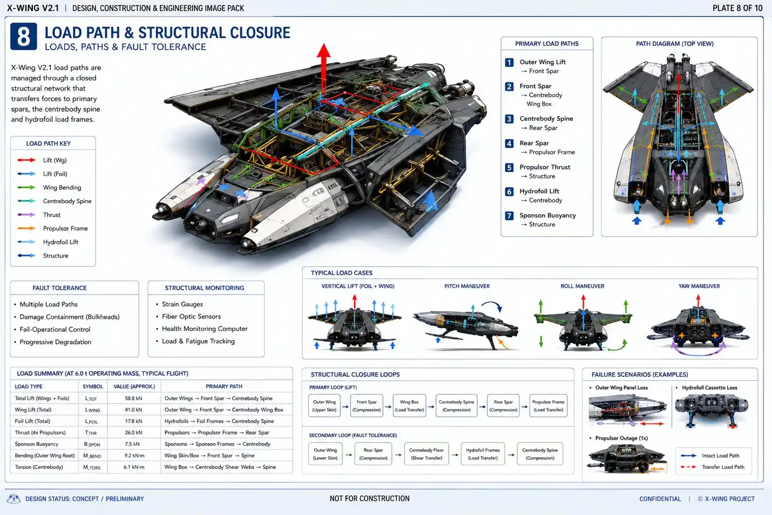
24. One structure carrying different worlds
X-Wing must survive load cases from both ships and aircraft.
A conventional aircraft is not normally designed for repeated wet-deck slamming.
A conventional small vessel is not normally designed for full aerodynamic wing bending.
X-Wing must carry both.
The structural model must eventually include:
- Aerodynamic wing bending
- Wing torsion
- Root-lock loads
- Propulsor thrust
- Propulsor gyroscopic loads where applicable
- Cross-deck torsion between sponsons
- Hydrofoil root bending
- Wet-deck pressure
- Bow and underside slamming
- Asymmetric water contact
- Hard landing
- Turning loads
- Towing and lifting loads
- Grounding and recovery loads
- Fatigue across repeated transition cycles
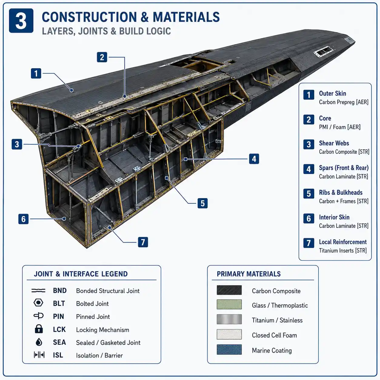
25. Primary aerospace structure
The centrebody should use:
- Carbon-fibre upper and lower spar caps
- Carbon or hybrid spar webs
- Deep forward and rear spars
- Composite skins contributing to torsional stiffness
- Full-depth root-locking bulkheads
- Continuous load paths into the propulsor and sponson frames
26. Marine and impact structure
The water-contact system should use tougher, more damage-tolerant materials where appropriate:
- Glass-fibre or thermoplastic-composite skins
- Moisture-resistant cores
- Replaceable bow structures
- Replaceable lower sponson shells
- Sacrificial foil leading edges
- Corrosion-isolated metallic attachments
- Drainage and inspection cavities
27. Metallic fittings and isolation
High-concentration loads may require titanium, stainless steel, or other corrosion-resistant fittings.
Those fittings must be isolated appropriately from carbon composites to prevent galvanic corrosion.
The design must include:
- Electrical bonding
- Lightning protection
- Moisture barriers
- Fire protection
- Accessible inspection
- Defined repair procedures
FAA composite guidance emphasizes that composite airworthiness depends on design, manufacturing control, environmental exposure, damage tolerance, inspection, maintenance, and repair — not merely material strength.
28. Structural-health monitoring
Embedded sensing may track:
- Strain
- Temperature
- Moisture
- Vibration
- Impact events
- Wing-lock loads
- Hydrofoil loads
- Propulsor-frame loads
Monitoring does not replace inspection. It improves the ability to target inspection and establish condition-based maintenance intervals.
Aerospace and Naval Structural Load Paths
Part IX — Failure reversion and maintenance
29. Failure must reduce capability, not instantly destroy the craft
X-Wing should not be designed around the assumption that every component will always work.
It should be designed around controlled degradation.
- Wing deployment fails
- Remain in surface mode.
- Wing lock is not confirmed
- Prohibit takeoff.
- One hydrofoil fails
- Abort transition and return to hull-borne operation where possible.
- One propulsor fails
- Continue at reduced capability or return to the water.
- Height sensors disagree
- Cross-check independent channels, reduce speed, increase clearance if safe, and land.
- Communications are lost
- Execute a predetermined safe behaviour.
- Structural load exceeds limits
- Automatically reduce speed or exit flight mode.
- Energy-system fault occurs
- Isolate the affected electrical section and preserve safety-control power.
The governing benchmark is:
No single credible failure should immediately force an uncontrolled transition from flight into the ocean.
Returning to the water is a successful outcome.
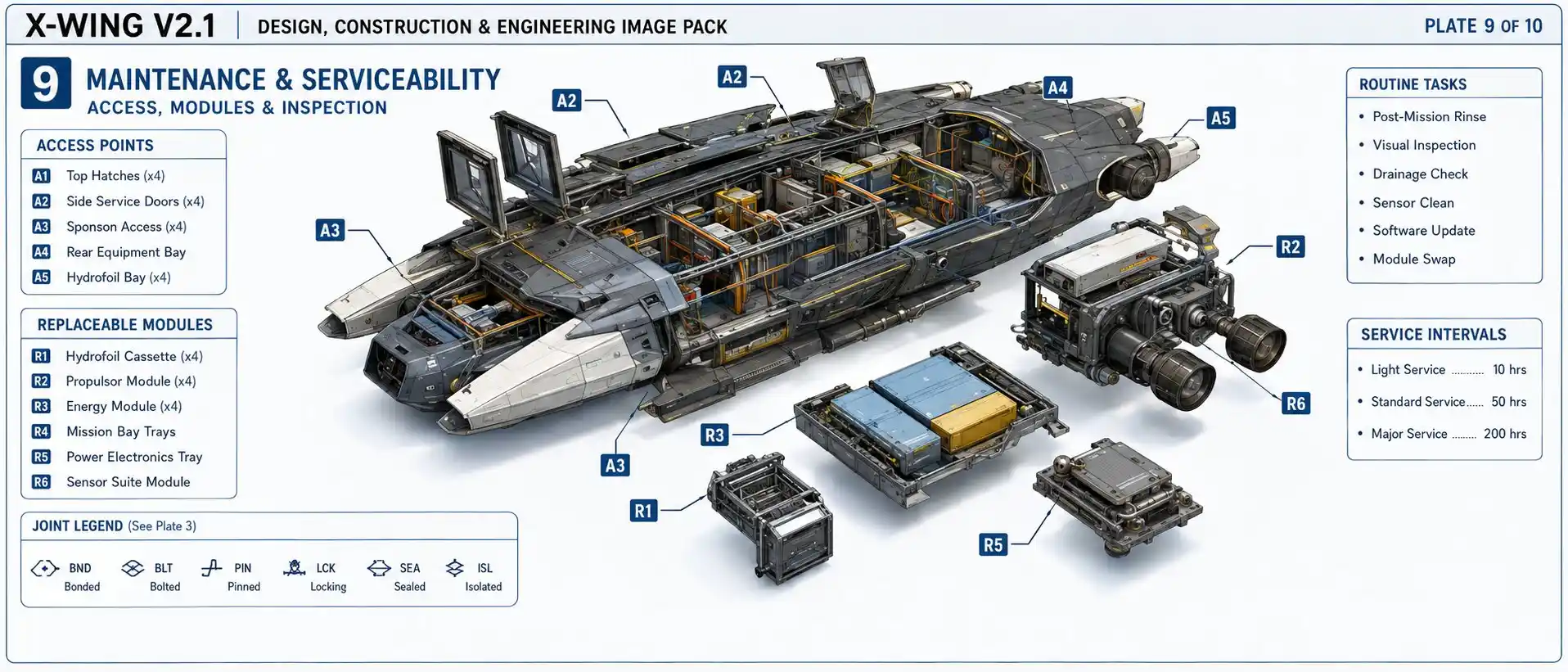
30. Replaceable modules
The following should be designed as replaceable units:
- Pusher propulsors
- Hydrofoil cassettes
- Sponson bow sections
- Lower impact shells
- Wing actuators
- Hinge-access modules
- Power-electronics modules
- Flight-control computers
- Sensor apertures where practical
A technically sophisticated vehicle that cannot be serviced efficiently will fail economically.
Failure Reversion, Maintenance, and Replaceable Modules
Part X — Modular internal architecture
31. Mission bay independence
The flight vehicle should not be redesigned for every role.
A standardized mission bay should define:
- Maximum mass
- Centre-of-gravity corridor
- Mechanical attachment points
- Power limits
- Cooling limits
- Data interfaces
- Software permissions
- Automatic module identification
Potential non-flight-critical applications include:
- Maritime observation
- Environmental monitoring
- Communications relay
- Search and rescue
- Emergency delivery
- Navigation support
- Fleet logistics
- Engineering test equipment
The mission module must not possess direct authority over flight-critical controls.
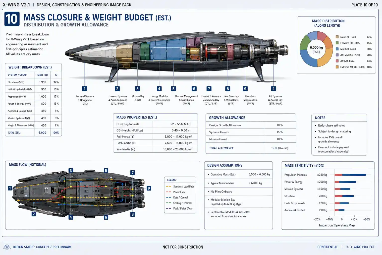
32. Mass and balance logic
The heaviest variable systems should remain close to the centre of gravity.
These include:
- Energy storage
- Mission equipment
- Major power electronics
- Replaceable internal modules
The centre of gravity must remain compatible with:
- Surface trim
- Foil-borne pitch control
- Ground-effect stability
- Landing
- Energy consumption over time
The centres of buoyancy, hydrofoil lift, and aerodynamic lift do not need to occupy exactly the same point, but their relationship must remain controllable throughout the transition.
Mass, Balance, Internal Volume, and Mission Bay
Part XI — Technical benchmark sheet
33. Mass and balance benchmarks
- Protected design-growth reserve
- Controlled empty-mass growth
- Verified centre-of-gravity range in every approved configuration
- Adequate reserve buoyancy after defined damage
- Mission mass near the centre-of-gravity region
- Safe balance as energy or fuel is consumed
- Separate subsystem mass budgets
34. Aerodynamic benchmarks
- Stable or actively controlled height behaviour
- Adequate pitch, roll, and yaw authority
- No unacceptable control reversal
- Predictable entry into and exit from ground effect
- Safe margin from stall and structural limits
- Acceptable behaviour across the approved centre-of-gravity range
- Safe degraded performance after a propulsor fault
35. Hydrodynamic benchmarks
- Stable hull-borne operation
- Predictable foil rise
- Controlled pitch during transition
- No persistent ventilation or cavitation within the approved envelope
- Clean water exit
- Safe water re-entry
- Controlled operation across representative wave headings
- Safe aborted takeoff
- Defined debris-impact tolerance
36. Structural benchmarks
- Flight loads carried through spars, frames, and locks
- No primary flight load carried solely by actuators
- Repeated deployment after saltwater exposure
- Detectable and repairable impact damage
- Replaceable marine-contact components
- Moisture and corrosion control
- Electrical bonding and lightning protection
- Fire isolation
- Fatigue life based on measured transition cycles
37. Autonomy benchmarks
- Independent height-sensing channels
- Forward wave-field prediction
- Sensor-confidence estimation
- Automatic rejection of unsafe transition
- Safe response to lost navigation
- Safe response to lost communication
- Deterministic emergency control
- Complete event and decision logging
- Hardware-in-the-loop failure validation
38. Maintenance benchmarks
- Rapid module replacement
- Accessible drainage and inspection
- Contamination-resistant locks
- Condition-based structural monitoring
- Defined inspection intervals
- Repair procedures before production
- Safe towing, lifting, and retrieval interfaces
39. Manufacturing benchmarks
- Limited structural material families
- Qualified joining and bonding processes
- Digital configuration control
- Traceable critical components
- Instrumented inspection
- Modular final assembly
- Repairable primary structure
- Sustainment cost included in design decisions
Part XII — Six product cycles
40. Product Cycle 0 — Simulation and subscale evidence
Validate:
- Geometry
- Lift and drag
- Ground-effect stability
- Sponson resistance
- Foil arrangement
- Spray interaction
- Propulsor interaction
- Fold clearance
- Structural load paths
- Wave-prediction algorithms
Use:
- Parametric CAD
- Mass modelling
- Aerodynamic CFD
- Hydrodynamic CFD
- Wind tunnels
- Tow tanks
- Wave basins
- Structural FEA
- Hardware-in-the-loop control
- Remotely operated scale vehicles
41. Product Cycle 1 — Autonomous surface vessel
Prove:
- Buoyancy
- Low-speed propulsion
- Navigation
- Collision avoidance
- Communications-loss recovery
- Marine endurance
- Maintenance access
No wings or hydrofoil flight requirement should distract from basic maritime reliability.
42. Product Cycle 2 — Autonomous hydrofoil vessel
Prove:
- Controlled foil rise
- Pitch and roll authority
- Ventilation detection
- Wave-response control
- Foil retraction or unloading
- Safe return to displacement mode
- Debris and failure response
43. Product Cycle 3 — Fixed-wing ground-effect demonstrator
Prove:
- Water takeoff
- Ground-effect stability
- Wave prediction
- Safe height control
- Landing
- Aborted transition
- Propulsion-out response
- Sensor-confidence logic
The fixed wing prevents folding complexity from obscuring the fundamental flight problem.
44. Product Cycle 4 — Folding-wing demonstrator
Prove:
- Fold motion
- Structural locking
- Alignment repeatability
- Saltwater sealing
- Drainage
- Contamination tolerance
- Repeated deployment cycles
- Surface operation after deployment failure
- Inspection and replacement of hinge components
45. Product Cycle 5 — Modular operational vehicle
Add:
- Standardized mission modules
- Broader operating conditions
- Fleet coordination
- Production-oriented structure
- Sustainment architecture
- Operational energy system selected from measured requirements
Each product cycle should retire one major uncertainty.
No cycle should conceal unresolved physics beneath additional capability.
Part XIII — Falsification criteria
A first-principles design must specify what evidence would weaken or invalidate it.
X-Wing should be substantially redesigned or discontinued if testing shows that:
- Empty structural mass consumes the useful energy and payload reserve
- Stable liftoff requires impractically high speed
- Foil-to-wing transition cannot remain controllable in modest waves
- Wing folding produces unacceptable root mass or fatigue
- Wave-following requires an altitude that eliminates the intended operating advantage
- Water-impact fatigue produces unacceptable structural life
- Propulsion mass produces inadequate endurance
- Cooling and corrosion maintenance dominate operating cost
- Safe failure reversion cannot be achieved
- The modular mission bay destabilizes surface, foil, or flight modes
- Production complexity makes the vehicle economically irrational
The concept is valuable only if it survives evidence.
Part XIV — Truthful signature management
46. Geometry
- Broad clean planform
- Aligned edges
- Integrated sensors
- Limited protrusions
- Controlled fold gaps
- Compact surface configuration
47. Materials and electrical integration
- Conductive composite design
- Electrical bonding
- Corrosion isolation
- Controlled apertures and interfaces
48. Thermal management
- Distributed heat spreading
- Shielded high-temperature equipment
- Controlled cooling paths
- Efficient operating modes
49. Acoustic, spray, and wake management
- Quiet low-speed persistence
- Reduced wake
- Clean foil transition
- Avoidance of large unnecessary spray plumes
50. Emission discipline
- Passive sensing where practical
- Limited transmissions
- Scheduled or directional communications
- No unnecessary continuous broadcast
The final truthful claim is:
X-Wing is not invisible. It is designed to make timely detection, confident classification, and continuous tracking more difficult by combining physical, environmental, thermal, acoustic, and operational advantages.
Part XV — The ten-image publication system
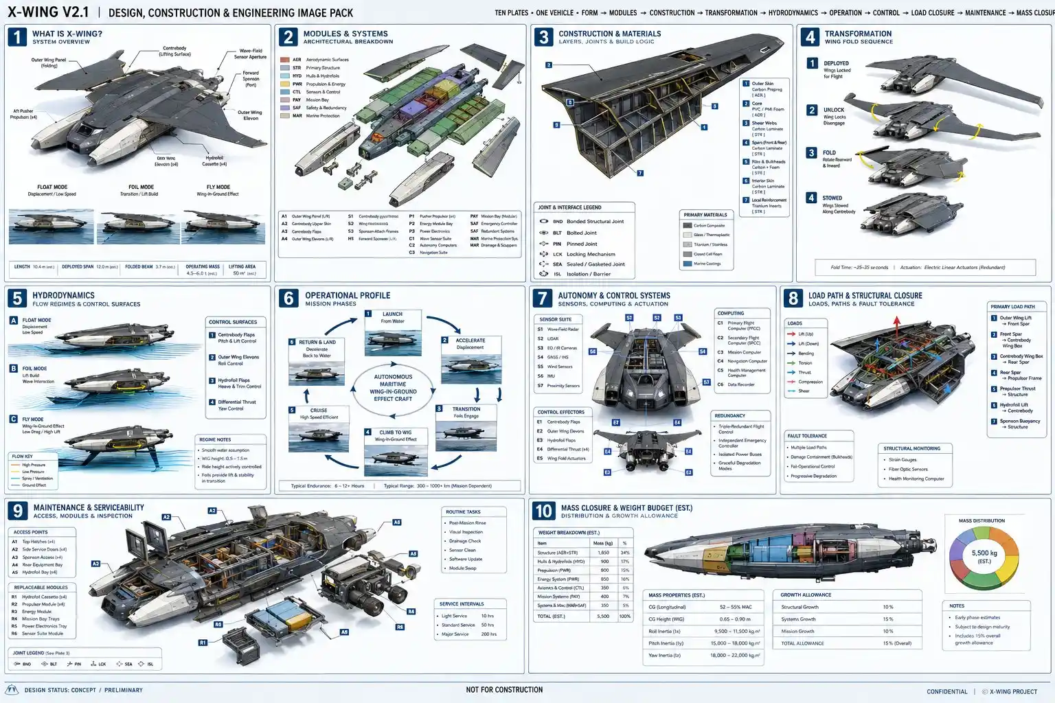
The ten plates are not supplementary decoration. They are a second engineering language running through the article.
Together they explain:
Form → internal architecture → transformation → hydrodynamics → transition → propulsion → control → loads → failure → balance
Every plate must preserve:
- The same geometry
- The same dimensions
- The same wing roots
- The same propulsor positions
- The same sponsons
- The same foil cassettes
- The same control surfaces
- The same internal zoning
- The same component identifiers
- The same material and colour map
The correct workflow is:
- Generate the clean unlabelled master rendering
- Audit geometry
- Generate subsystem views from the accepted reference
- Add controlled vector labels
- Apply dimensions and legends
- Audit all ten plates as one system
Generated text should not be trusted for final technical labels.
Part XVI — What remains unknown
The following cannot yet be claimed:
- Final maximum operating mass
- Final wing area
- Final wing loading
- Final hydrofoil arrangement
- Transition speed
- Liftoff speed
- Cruise speed
- Range
- Endurance
- Useful wave-height limit
- Crosswind limit
- Gust tolerance
- Structural life
- Final propulsion system
- Cooling performance
- Wing-lock cycle life
- Unit cost
- Production rate
- Maintenance hours per operating hour
- Signature levels
- Communications resilience
- Final classification and regulatory pathway
Architectural coherence is not demonstrated capability.
Part XVII — Final scores
These scores evaluate the current design architecture and publication system, not completed hardware.
Article and narrative
- Narrative architecture: 9.8/10
- First-principles structure: 9.8/10
- Truth and uncertainty discipline: 9.8/10
- Technical readability: 9.7/10
- Balance of paragraphs and structured bullets: 9.7/10
- Image-to-article synchronization: 9.8/10
Engineering architecture
- Operating-layer logic: 9.5/10
- Aerodynamic architecture: 9.4/10
- Hydrodynamic architecture: 9.2/10
- Folding-wing architecture: 9.3/10
- Structural architecture: 9.4/10
- Mechanical integration: 9.4/10
- Naval-engineering coverage: 9.5/10
- Autonomy and control: 9.6/10
- Failure tolerance: 9.6/10
- Modularity: 9.5/10
- Manufacturability concept: 9.2/10
- Product-cycle sequencing: 9.8/10
Visual architecture
- Ten-image narrative coherence: 9.8/10
- Component and label system: 9.6/10
- Prompt-pack maturity: 9.8/10
- Canonical geometry definition: 9.2/10
- Potential publication quality: 9.7/10
Overall architectural score
9.5/10
This is approximately the maximum honest score available before simulation and hardware.
Readiness to begin formal parametric engineering
9.6/10
Readiness for physical prototype construction
Approximately 5/10
Readiness for production engineering
Approximately 4/10
Demonstrated vehicle capability
Not yet scoreable
Conclusion — A new vehicle category must be earned
X-Wing waits on the ocean.
Its wings are folded. Its weight is carried by water rather than propulsion. It can remain present without remaining airborne.
When speed becomes valuable, the vehicle changes state.
The panels deploy and lock.
The hydrofoils lift the sponsons.
The water releases the craft gradually as aerodynamic lift assumes the load.
X-Wing moves into the thin operating layer immediately above the sea — not because low flight is visually dramatic, but because the complete architecture has been shaped around that environment.
Later, the vehicle returns.
- Its greatest advantage is not that it can fly continuously.
- Its greatest advantage is that it does not have to.
- It can use buoyancy for persistence, hydrodynamic lift for transition, and aerodynamic lift for speed. It can abandon flight when conditions, energy, system health, or mission value no longer justify it.
That combination could establish a new operating class between the autonomous surface vessel and the conventional aircraft.
But the class will not be created by a name, an image, or an ambitious claim.
It will be created only if one coherent machine can repeatedly complete the whole cycle:
Float. Foil. Fly. Return. Recover. Repeat.
X-Wing should not ultimately be judged by how futuristic it appears in a technical rendering.
It should be judged by whether the same vehicle can cross the boundary between sea and air thousands of times without losing control, structural integrity, maintainability, truth, or economic purpose.
X-Wing V2.1 — Design, Construction, and Engineering Atlas
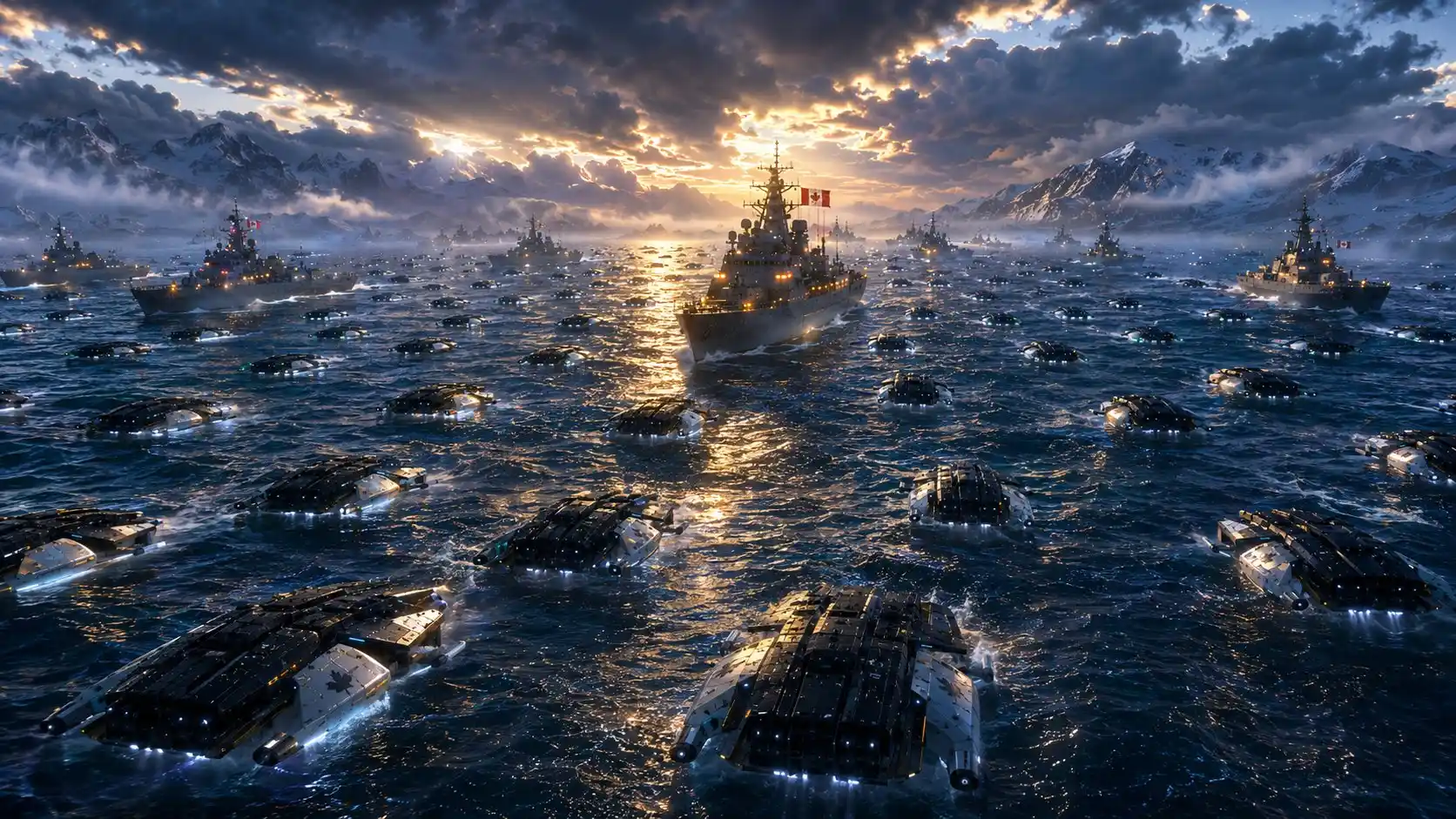
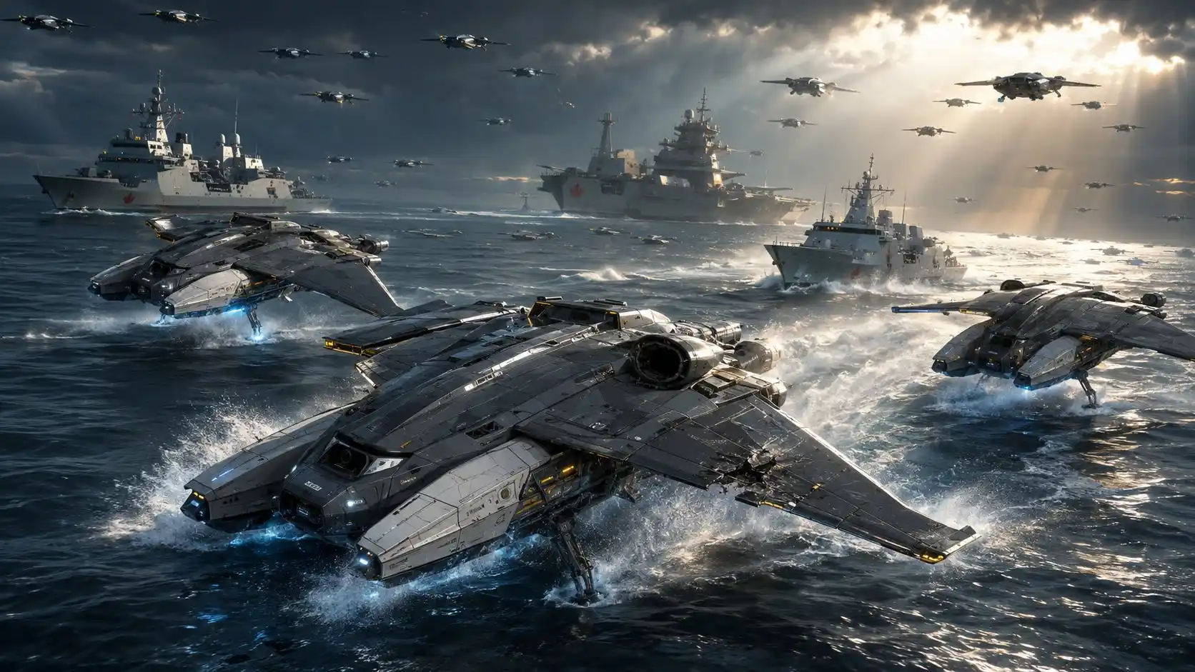
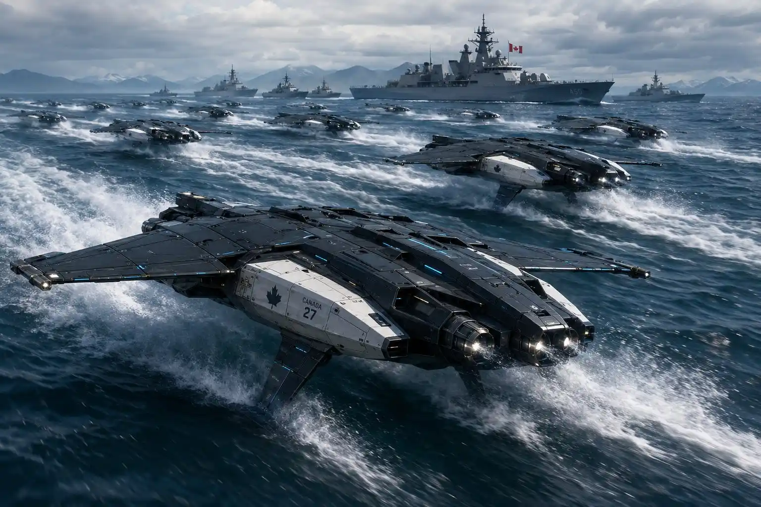
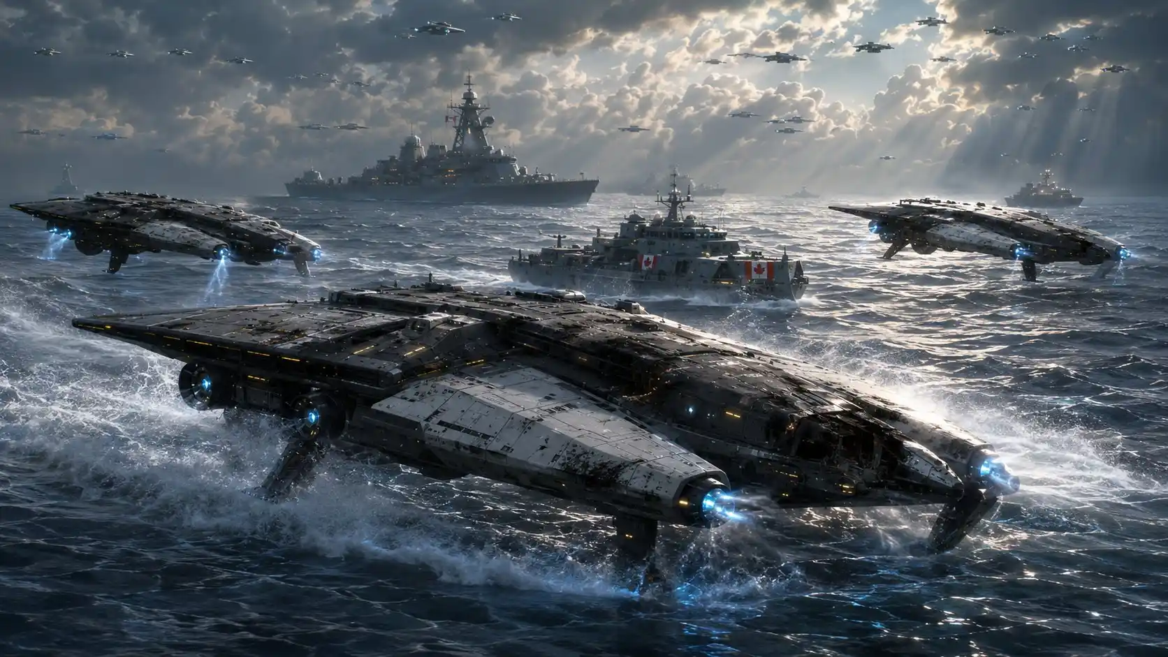
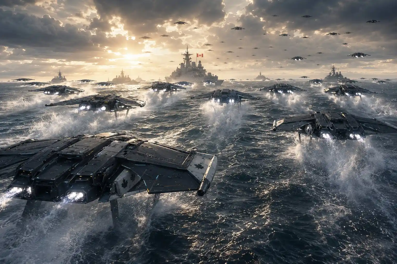
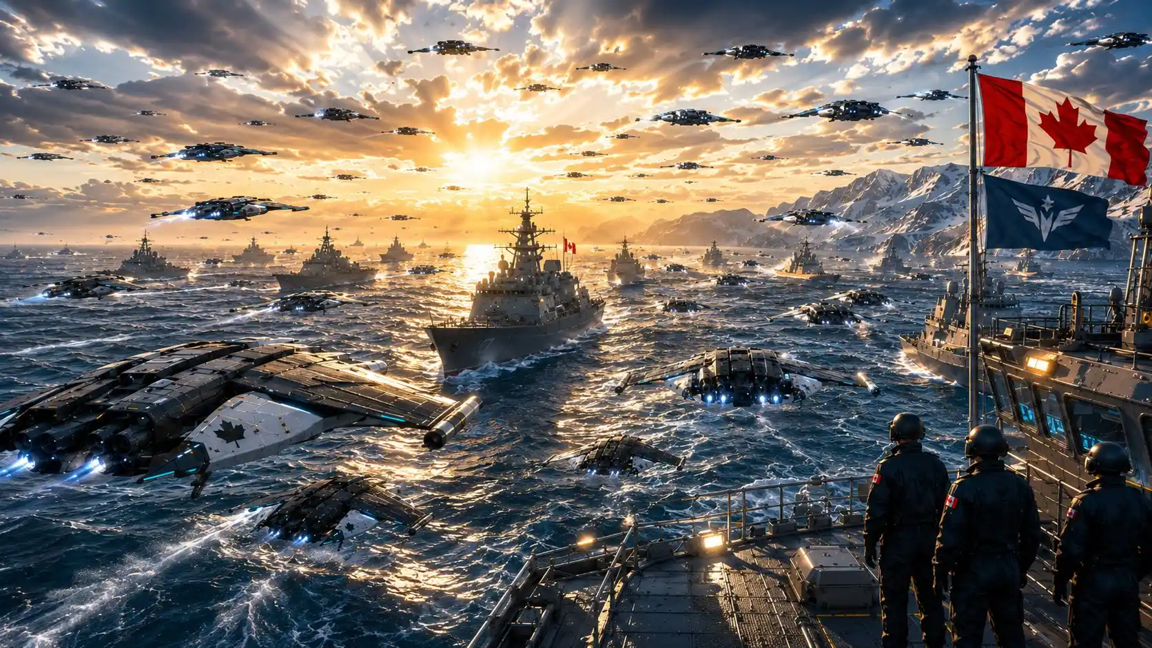
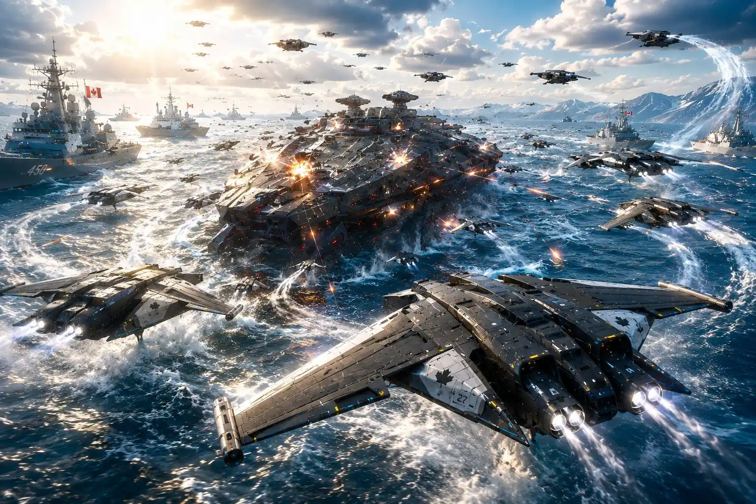
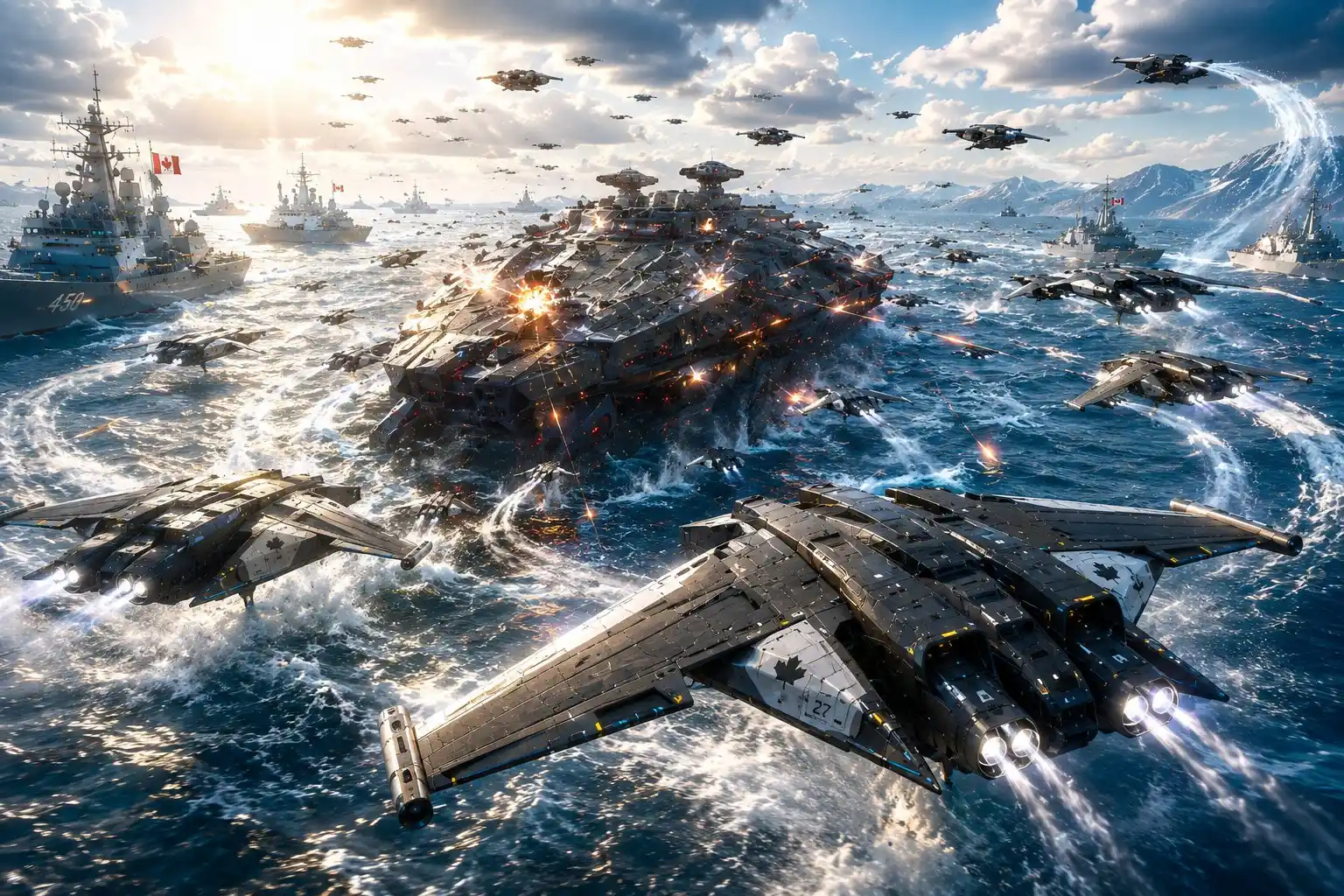
X-Wing V2.1 — When the Navy Becomes the Sky Fleet
Ten Cinematic Operational Concept Renderings of the Next-Generation’s TNG Maritime Swarm
📘 “BLUE GUARD: The Hidden War” https://x.com/SkillsGapTrain/status/1941771675550482760
Appendix A — Media Formation, Star Trek TNG “7×12” – Pegasus, Legacy Generation Age
I Bet You never thought you See me Again. https://youtu.be/xQ25Y6NTkSo
Star Trek TNG – Pegasus https://youtu.be/HdOSFhSbZgU
Romulan Warbird Decloaking Ahead https://youtu.be/HdOSFhSbZgU
Without wills Loyalty none of us would have survived. https://youtu.be/BJvQqM6vPrQ
Mutiny on a Federation Starship? https://youtu.be/KsEX0N4us4g
What the Hell is going on here Will? https://youtu.be/Oc2RR_PfGzw
It was wrong 12 years ago and its wrong today. https://youtu.be/C9HGnU9gjbM
That treaty is the biggest mistake we ever made. https://youtu.be/dnnVNhDlNMM
Disengage the Cloak. https://youtu.be/uY65X0AJ0f0
Your going to need your friends. https://youtu.be/ArZTc8peUiA
Appendix B — Media Formation, The X-Wing Story, Next Generation Age
Eminem – Lose Yourself https://youtu.be/_g3XPXrkgfo
Eminem – Not Afraid https://youtu.be/_g3XPXrkgfo
OST Pirates of the Caribbean – Marry me (Main Theme Will and Elizabeth) https://youtu.be/owTU6iVTQsM