Structure, Lift, Nacelles, Doors, Batteries, Hydrogen, Electronics, Q, Digital Twin, and D.A.N.G.E.R.
Designed by: Skills Gap Trainer
SGT-TNG Master Architecture Book — Public X Series File 3 of 5
Purpose: expand the compressed engineering skeleton into an expert-readable technical architecture page without implying certification, airworthiness, road-worthiness, production readiness, or passenger approval.
Core doctrine: the machine becomes serious only when the reader can follow the chain from physics to requirement, from requirement to interface, from interface to failure mode, from failure mode to proof gate, and from proof gate to public claim boundary.
Build Identity and Claim Boundary
- This file is X Page 3 of the five-file public reconstruction series.
- File 1 established the thesis and the icon: D.E.L.O.R.I.A.N. as the road-first captain’s capsule and public hero.
- File 2 established the framework: NAV-CF, Model A, Model B, Model C, BOOM 1971, A.R.G.O., mission kits, and branch discipline.
- File 3 enters the engineering: structure, lift, energy, controls, Q, digital twin, D.A.N.G.E.R., and the technical proof chain.
- This is still concept architecture. It is not a certified aircraft, not a certified road vehicle, not a production engineering package, and not a flight-test approval.
- The document uses no tables. Registers are presented as bullets so the text remains portable to X, WordPress, long-form posts, and public review threads.
Engineering Thesis
The most important engineering fact about D.E.L.O.R.I.A.N. 001 SGT-TNG is that it cannot be judged as a car with decorative flight parts. It has to be judged as a road-first vehicle whose optional flight layer imposes aircraft-grade truth on the body, the doors, the energy system, the software, the service workflow, and the public claims. The body can be beautiful, but beauty is not the authority. Physics is the authority. Mass, lift, heat, structure, control, and evidence are the authorities.
That is why the engineering spine must start from first principles instead of product adjectives. A road vehicle can hide a great deal of internal complexity from the public. An aircraft cannot. An aircraft has to account for weight, load path, vibration, thermal endurance, redundancy, surface state, weather, operator state, software state, service state, and configuration history. A roadless mobility vehicle inherits both domains. It carries the emotional gravity of a car and the evidence burden of a powered-lift aircraft.
The architecture therefore rejects the lazy phrase “flying car” when that phrase means spectacle before proof. The more disciplined phrase is road-first captain’s capsule with a modular flight layer. The road body is not merely a cabin hanging from a drone. The wing and nacelle layer is not a flying crane that happens to pick up a car. The car is the core vehicle, the capsule protects continuity, the wing system provides the access-to-sky layer, and the surrounding framework decides when the machine is permitted to change state.
For experts, the central question is not whether the render looks exciting. The central question is whether the concept knows where its hard problems live. This file is built to show that it does. The hard problems are total mass, hover power, disk loading, downwash, noise, battery peak power, thermal repeatability, nacelle load paths, door clearance, structural retention, crash protection, hydrogen safety, software assurance, digital twin truth, service workflow, and claims discipline. None of those can be solved by style. But style can become useful when it keeps the vehicle desirable enough for the public to care about the proof path.
A serious architecture has to hold two truths at once. First, the D.E.L.O.R.I.A.N. / NAV-CF system is a powerful and coherent design direction. Second, the system is not yet proven as hardware. This is not weakness. It is the beginning of technical honor. The strongest concept is not the concept that claims victory early. The strongest concept is the one that identifies its own proof gates before the public or the regulator has to ask.
The First-Principles Chain
- Mass drives everything: tire load, braking, crash energy, hover power, battery size, wing area, structure, cost, and service workflow.
- Hover is the tax: every second spent hovering consumes extraordinary power compared with efficient wing-borne cruise.
- Cruise is the dividend: the wing exists to reduce the energy burden after vertical access is achieved.
- Reserve is the safety margin: range without reserve is not mature mobility; it is a publicity number.
- Heat is truth: battery, inverter, motor, fuel-cell, cabin, and brake heat must be repeatable, not merely survivable once.
- Interfaces are destiny: a mission kit, nacelle, door, Q module, battery pack, or hydrogen module is only safe if its interfaces are controlled.
- Unknown state means no flight: unknown door state, unknown nacelle lock state, unknown energy state, unknown configuration state, or unknown service state must block the transition into flight.
- Human authority must remain real: Q may explain, diagnose, and recommend; D.A.N.G.E.R. may protect thresholds; neither system becomes sovereign over the human.
- Proof precedes claim: simulation, ground article, tethered test, flight envelope expansion, acoustic measurement, thermal cycling, service trials, and regulatory engagement must come before public passenger claims.
1. Structure and Layout
The structural problem begins with a paradox: the vehicle must look like a desirable road machine while carrying the hidden seriousness of a powered-lift system. If the structure is designed only as a car, the roof cannot responsibly accept a flight module. If the structure is designed only as an aircraft, the road appeal collapses into a utility pod. The SGT-TNG answer is a capsule-plus-keel architecture: a strong road-first occupant capsule with a load-conscious lower structure, rear balance mass, roof/rear hardpoints, and controlled interfaces for the modular wing/nacelle layer.
The capsule is the human space. It must provide visibility, entry, restraint, crash protection, service access, and psychological trust. The keel is the engineering spine. It carries energy mass, road load, landing load, and the consequences of modular attachment. The roof/rear structure is not cosmetic. It becomes the flight-kit interface region, which means it must be treated like a structural system rather than a styling surface.
The most dangerous mistake is to treat the roof wing mount as an accessory. A roof rack carries cargo. A flight-kit hardpoint carries load, vibration, reaction torque, inspection burden, and public trust. The architecture therefore places the wing assembly behind the main door zone, over the rear passenger / rear roof structure, where it can connect to stronger body regions without blocking the Captain’s Egress Bay.
Structural Requirements Register
- STR-001: The primary occupant capsule must remain the non-negotiable human-protection volume.
- STR-002: The lower body must include a keel-like structural logic capable of distributing road, landing, battery, and flight-kit loads.
- STR-003: Rear mass placement must support balance without turning the rear quarter into an ugly cargo box or aircraft pylon.
- STR-004: Roof/rear hardpoints must be treated as flight-critical interfaces, not decorative mounts.
- STR-005: Door frames must preserve stiffness when the access system is open, closed, or under service inspection.
- STR-006: Nacelle load paths must enter reinforced structure, not thin outer skin.
- STR-007: Service panels must not require destructive disassembly or secret factory-only access for routine inspection.
- STR-008: Road-mode crash protection must not be sacrificed for flight-module styling.
- STR-009: Flight-module attachment must be inspectable by trained technicians using documented procedures.
- STR-010: Any structural claim must remain provisional until load analysis, coupon testing, subassembly testing, and full-vehicle ground testing exist.
Structural Failure Modes
- A roof mount that looks clean but does not distribute loads into the capsule and lower structure.
- A rear battery layout that improves center of gravity but damages crash performance or service access.
- A door opening that is visually dramatic but weakens the side frame and creates torsional problems.
- A hardpoint that passes static loads but fails under vibration, fatigue, inspection misses, or repeated thermal cycling.
- A body panel that is mistaken for structure because the render shows it carrying a nacelle beautifully.
- A service workflow that cannot reliably find cracks, loosened fasteners, corrosion, seal failures, connector fatigue, or post-incident damage.
2. Lift Architecture
The lift architecture has to be honest about the difference between vertical access and efficient travel. Vertical lift is valuable because it removes dependence on roads, bridges, ferry terminals, short runways, and clear ground corridors. It is also expensive in power. Wing-borne travel is valuable because it lets the vehicle move efficiently after it has paid the hover tax. That is why the architecture cannot be judged as a pure multirotor spectacle. The wing exists because the system must eventually escape the energy burden of hover.
The D.E.L.O.R.I.A.N. / NAV-CF concept therefore treats vertical lift as a gateway state and wing-borne travel as the maturity direction. The vehicle may use distributed lift units, nacelles, and a flight module, but the system logic is not “hover everywhere.” The system logic is “use vertical capability to access the air, then use aircraft principles to travel.” This is the difference between a novelty and a mobility layer.
Every lift decision creates a body decision. If the rotors or propulsors are too close to the doors, egress suffers. If the wing assembly is too high, the vehicle becomes a carrier drone instead of an integrated road-first aircraft. If it is too far forward, it conflicts with the driver area and primary access doors. If it is too far back, the vehicle may lose balance or become visually and structurally awkward. The correct location is a narrow band: rear of the main door zone, low over the rear roof/passenger structure, with symmetrical left and right nacelles and an unbroken span.
Lift Requirements Register
- LFT-001: Hover must be treated as an energy tax, not the default travel mode.
- LFT-002: Wing-borne travel must be the long-term efficiency target, because motors do access and wings do travel.
- LFT-003: Propulsor placement must preserve door clearance, head clearance, ground safety, and service access.
- LFT-004: Disk loading, downwash, and noise must be measured before any public comfort or neighborhood compatibility claim.
- LFT-005: Nacelle symmetry must be preserved; unequal nacelles or distorted wing length cannot be treated as acceptable design drift.
- LFT-006: Transition from vertical to forward flight must be a proof-gated engineering domain, not a visual assumption.
- LFT-007: Emergency descent assumptions must be stated as assumptions until flight testing demonstrates behavior.
- LFT-008: The vehicle must never imply certified passenger flight before the regulatory and test evidence exists.
Hover, Disk Loading, Downwash, and Noise
The public often imagines vertical flight as a clean visual trick: the vehicle rises, the camera follows, and the city becomes free. Engineering sees something harder. Hover requires the aircraft to accelerate air downward. The smaller the effective disk area relative to weight, the harsher the induced velocity, downwash, acoustic signature, debris hazard, and ground interaction may become. This does not make the concept impossible. It makes disk area, rotor/propulsor design, ground clearance, operating corridor, and mission profile central to the architecture.
For this reason, the report must not claim quiet urban operation merely because the render looks calm. It can claim that acoustic footprint, downwash, and ground interaction are recognized as proof gates. It can claim that the vehicle architecture must be tested against powered-lift and rotorcraft reality. It cannot claim neighborhood compatibility, vertiport readiness, or routine passenger operation without measured data.
The correct engineering posture is disciplined optimism. The concept is allowed to be beautiful. It is allowed to be ambitious. It is not allowed to convert beauty into acoustic proof. The proof must come from physical models, rotor/propulsor sizing, computational analysis, ground tests, tethered hover, instrumented hover, and repeated thermal/acoustic measurement.
3. Wing Module and Nacelles
The wing-and-nacelle module is the most visually tempting part of the project and therefore one of the easiest places to lose engineering discipline. It must never become a separate drone that carries the car. It must never float above the vehicle like a logistics aircraft. It must never become a roof cannon, a decorative rack, or a random set of glowing pods. In the locked design doctrine, the flight module is a physically attached, low-mounted, rear-zone wing system that connects to the vehicle’s own structural hardpoints.
The wing is a continuous structural idea from left nacelle to right nacelle. The left and right sides must read as the same system, not one normal wing and one shortened wing. The nacelles are not loose engines; they are load-bearing, serviceable propulsion stations integrated with the wing and the hardpoint architecture. They must clear the door path, clear the human egress path, and remain reachable for inspection.
The image process revealed the hidden requirement. When the wing was placed over the driver area, it fought the gullwing door. When the doors became too wide, the model raised the wing five feet above the car, turning the concept into a drone carrier. When the wing moved too far back, the visual balance and structural logic suffered. The engineering answer was not to abandon the door or the wing. The answer was to split the access system and move the wing module into the rear roof/passenger hardpoint zone.
Nacelle and Wing Requirements Register
- NAC-001: The wing module is attached to the vehicle, not suspended over it.
- NAC-002: The wing module sits low and clean behind the main door zone, over the rear passenger / rear roof structure.
- NAC-003: The wing is one continuous span from left nacelle to right nacelle when deployed or shown in flight-ready state.
- NAC-004: Left and right nacelles must be symmetrical in size, position, and visual authority.
- NAC-005: No extra hidden engines, floating pods, or third nacelles are acceptable in the design canon.
- NAC-006: Ground-detachable does not mean flight-detachable; in flight the module must be captive, locked, retained, and state-confirmed.
- NAC-007: Mechanical lock, geometry capture, second-path retention, and digital confirmation must all be considered before any flight-state release.
- NAC-008: The system must assume inspection misses are possible and design the workflow to catch them before flight.
- NAC-009: No software-only release is acceptable for flight-critical retention.
- NAC-010: Unknown nacelle state means no flight.
4. Door Architecture and Captain’s Egress Bay
The door architecture is not a styling footnote. It is one of the central engineering discoveries of the project. The vehicle inherits the emotional value of a gullwing or dihedral door, but it cannot simply use a giant one-piece door that sweeps into the wing module. That would force the wing higher, push nacelles into awkward places, and turn human access into a conflict with flight geometry. The correct answer is a split access system.
The upper door carries the inheritance. It rises compactly, creating the command entrance, the visual ceremony, and the executive identity. The secondary section handles the practical egress volume. It can slide rearward or fold rearward from the vertical rear edge of the opening, creating a comfortable human path without requiring the upper gullwing to consume the entire side of the vehicle. This is how the design protects both soul and clearance.
The Captain’s Egress Bay is the clear human volume created by this decision. It is not merely a door opening. It is the protected path by which a driver or passenger can enter, exit, stand, turn, and move without being trapped by nacelles, wing roots, oversized door panels, or styling triangles. In the engineering book, this becomes a requirement: human egress is not subordinate to visual drama.
Door Requirements Register
- DOR-001: The upper door must be compact enough to avoid interference with the rear-zone wing assembly.
- DOR-002: The secondary access panel must slide rearward or fold rearward along the rear edge of the opening to improve entry and exit.
- DOR-003: The rear edge of the main opening should remain visually and functionally disciplined; it must not stretch into a random triangular cutout.
- DOR-004: Door state must be sensed, confirmed, logged, and understood by Q and D.A.N.G.E.R.
- DOR-005: Unknown door state means no flight.
- DOR-006: Unknown door lock state means no flight.
- DOR-007: Emergency ground release must exist, but in-flight release must be inhibited by state, load, and mode logic.
- DOR-008: Door structure must preserve crash and side-frame stiffness; the opening cannot become a beautiful weakness.
- DOR-009: The egress path must be validated with human factors, not only visual composition.
- DOR-010: Door design claims must remain concept-level until mockup, ergonomics, latch, seal, crash, and lock testing exist.
5. Road Architecture
D.E.L.O.R.I.A.N. is road-first because daily usefulness is the anchor. If the vehicle is unpleasant, awkward, or visually unserious on the road, it loses the public before the sky layer can even be explained. Road-first does not mean the flight layer is fake. It means the vehicle’s first claim to civilization is that it can be driven, understood, serviced, and loved as a machine before it asks permission to rise.
The road architecture must therefore respect normal hard truths: mass, braking, tire load, cooling, stability, crash energy, charging, service access, and occupant comfort. A road-first vehicle with a flight module is heavier and more complex than a pure sports car. It may still aim for hyper-GT emotional territory, but it must be honest about the mass penalty of structure, batteries, wing hardpoints, nacelle interfaces, redundant electronics, cooling, and safety systems.
The road body is also the adoption engine. The public does not fall in love with an interface diagram. It falls in love with a machine that seems to belong in the future. The engineering danger is that public beauty can tempt overclaiming. The engineering opportunity is that beauty can make people care enough to read the proof path.
Road Requirements Register
- RD-001: The vehicle must remain visually and functionally credible in road mode.
- RD-002: Road-only operation must be possible without forcing the owner to carry every flight-state burden at all times.
- RD-003: Braking, tires, suspension, steering, and thermal management must be sized around real mass, not render mass.
- RD-004: Flight-module interfaces must not compromise ordinary road service access.
- RD-005: Crash protection must not be sacrificed for wing integration.
- RD-006: The road cabin must remain premium, legible, and human-centered.
- RD-007: Performance estimates must remain estimates until prototype measurement exists.
- RD-008: Road claims must be separated from flight claims; a strong road concept does not prove aircraft readiness.
6. Battery, High-Voltage, and Thermal Architecture
The battery system is the baseline energy architecture for the first civil proof branch. It is not chosen because batteries are magic. It is chosen because a battery-electric baseline is the clearest path to ground testing, road operation, peak-power delivery, repeatable diagnostics, and early prototype control. In the architecture, battery does the first proof. Hydrogen may later extend endurance, but hydrogen should not be used to hide an immature first vehicle.
Peak power is the central battery challenge. VTOL lift and high-performance road operation can both demand intense power bursts. The pack must support the current, the voltage, the thermal rejection, the safety isolation, the contactor logic, the crash protection, and the post-incident handling burden. A pack that performs once in a render does not prove repeatability. The real proof is repeated high-load operation followed by safe service, safe charging, safe storage, and safe degraded-state handling.
Thermal repeatability is the hidden maturity test. If the vehicle can lift once but cannot cool down predictably, it is not mature. If it can accelerate once but then derates unpredictably, it is not mature. If it can pass a short demo but cannot handle a service cycle, it is not mature. Heat is where many beautiful concepts become real engineering projects.
Battery and HV Requirements Register
- BAT-001: Model A should remain battery-electric as the first civil proof baseline.
- BAT-002: Battery architecture must support peak power, not merely nominal energy capacity.
- BAT-003: Thermal management must be designed for repeatability across road, hover, transition, charging, and degraded operation.
- BAT-004: HV isolation must be monitored, logged, and visible to service procedures.
- BAT-005: Pack placement must support center of gravity, crash protection, service access, and fire/emergency response logic.
- BAT-006: Battery damage after crash, flood, heat event, or service incident must trigger conservative no-go handling.
- BAT-007: Charging claims must be separated from pack chemistry, voltage architecture, cooling, infrastructure, and proof state.
- BAT-008: Battery state must be part of the digital twin and part of the D.A.N.G.E.R. threshold model.
7. Hydrogen Fuel-Cell-Up Architecture
Hydrogen belongs in this architecture as a future endurance layer, not as a shortcut around battery physics. The fuel-cell-up branch is valuable because roadless mobility may eventually require longer missions, remote service, cold-weather resilience, and field endurance that pure battery architecture cannot satisfy easily. But hydrogen also adds tanks, pressure, valves, leak detection, thermal burden, refueling workflow, codes and standards, emergency-response procedures, and service complexity. It is powerful only when it is honest.
The clean principle is: battery for peak power, fuel cell for endurance, buffer battery for transients, motors for performance, digital twin for truth, Q for explanation, D.A.N.G.E.R. for threshold protection, human authority over all. This separates energy roles instead of pretending one technology solves everything. The fuel cell should not be asked to handle every transient. The battery should not be asked to provide unlimited endurance. The digital systems should not be allowed to hide energy uncertainty behind attractive user-interface language.
Hydrogen also changes the safety case. A hydrogen vehicle is not merely an electric vehicle with a different energy source. It carries compressed gas, venting logic, sensor requirements, refueling protocol, inspection burden, and emergency responder training needs. That is why the concept keeps hydrogen as a later Model B / rugged branch study rather than the first civil baseline.
Hydrogen Requirements Register
- HYD-001: Hydrogen is an endurance layer for later branches, not the first civil proof baseline.
- HYD-002: The architecture must separate fuel-cell steady output from battery peak-power demand.
- HYD-003: Buffer battery must handle transients, hover bursts, and power smoothing where applicable.
- HYD-004: Hydrogen state truth must include pressure, temperature, valve state, leak state, stack state, cooling state, and service history.
- HYD-005: Hydrogen storage must be treated as a packaging, crash, venting, service, and emergency-response problem.
- HYD-006: Refueling workflow must be defined before any field-endurance claim.
- HYD-007: Hydrogen safety must reference appropriate codes, standards, and first-responder practices before public deployment.
- HYD-008: Hydrogen must never be used as a rhetorical fix for an overweight or under-cooled design.
8. Electronics, Controls, and Software Assurance
The vehicle’s electronics are not decoration. They are the nervous system by which the vehicle understands itself. A road-first powered-lift concept has to coordinate high-voltage battery, low-voltage systems, inverters, motor controllers, sensors, latches, nacelle locks, flight controls, road controls, thermal systems, Q interface, digital twin logging, and D.A.N.G.E.R. no-go logic. If those systems are treated as consumer-device features, the architecture fails. If they are treated as auditable safety-relevant systems, the architecture becomes serious.
The flight-control challenge is especially important because a compound or transition-capable VTOL vehicle does not have one simple operating mode. It has road state, static service state, flight-module docked state, flight-module confirmed state, hover state, transition state, wing-borne state, degraded state, emergency landing state, and recovery state. Each state must have allowed actions and forbidden actions. A beautiful dashboard is not enough. The system needs mode logic, requirement traceability, fault handling, and verification evidence.
The software boundary is where the human-command doctrine becomes technical. Q explains; Q does not rule. D.A.N.G.E.R. blocks unsafe transitions; D.A.N.G.E.R. does not become reckless autonomy. The vehicle may assist the operator, but every assistance feature must be bounded by operational design domain, state truth, fallback behavior, and claim discipline.
Electronics and Controls Requirements Register
- ELEC-001: HV and LV architectures must be separated, documented, serviceable, and monitored.
- ELEC-002: BMS, inverter, motor controller, latch controller, nacelle controller, and flight controller states must be visible to diagnostic logic.
- ELEC-003: Mode transitions must be explicit: road, service, docked, confirmed, hover, transition, cruise, degraded, emergency, recovery.
- ELEC-004: Software assurance must be planned before flight-critical automation claims.
- ELEC-005: Sensor failure must not produce false confidence; unknown state must be treated conservatively.
- ELEC-006: Cybersecurity must protect configuration, command, diagnostics, updates, and service history.
- ELEC-007: Remote/cloud assistance must not become required for immediate safe operation or recovery.
- ELEC-008: Human-readable explanation must be available without hiding behind proprietary black-box status codes.
9. Q Module
Q is the explanation intelligence of the architecture. It is not a god layer, not a sovereign pilot, not a marketing chatbot, and not a cloud leash. Q is the system that helps the human understand the vehicle: what state it is in, what changed, what is safe, what needs inspection, what is unknown, what is degraded, and what must not be attempted. In a mature architecture, Q turns complexity into readable responsibility.
The removable Q module idea matters because it makes intelligence continuity visible. If the vehicle is damaged, lost, or disabled, Q can preserve repair instructions, diagnostic history, configuration records, maps, manuals, and emergency guidance. That does not make Q magical. It makes Q a portable continuity node. The human can take Q, power it independently, and preserve knowledge beyond the vehicle. That is a powerful civilization idea, but it must remain bounded: Q advises and explains; it does not command illegally, secretly, or without human authority.
Q also gives the open manual culture a living interface. A thousand-page manual can be intimidating. Q can translate the manual into situation-specific explanation. But the manual must remain real. If Q disappears, the manual still exists. If the network fails, the vehicle still has local truth. If the owner changes country or shop, the configuration and service logic remain inspectable.
Q Requirements Register
- Q-001: Q explains vehicle state in human language.
- Q-002: Q supports diagnostics, configuration awareness, service history, and manual navigation.
- Q-003: Q must be modular and potentially removable as a continuity device, while remaining protected against casual theft or unauthorized use.
- Q-004: Q must not become sovereign over the human operator.
- Q-005: Q must not hide uncertainty; it must clearly state unknown, degraded, blocked, or no-go conditions.
- Q-006: Q must preserve local usefulness during network loss.
- Q-007: Q must support open-source literacy without exposing unsafe control pathways.
- Q-008: Q must be separable from D.A.N.G.E.R.; explanation and threshold protection are related but not identical functions.
10. Digital Twin
The digital twin is the trust record of the vehicle. It is not merely a 3D model. It is the configuration history, service state, inspection record, software state, energy state, mission-kit state, fault history, proof state, and return-to-service evidence. A vehicle that can change between road and flight-relevant configurations cannot depend on memory, assumptions, or owner enthusiasm. It must know what it is.
No trusted state, no flight. This is one of the strongest doctrines in the architecture. If the vehicle cannot prove which module is attached, which version is installed, which inspection is current, which faults are unresolved, which software is active, which battery state is valid, which door latches are confirmed, which nacelle locks are retained, or which mission kit has been approved, then it cannot responsibly enter flight mode.
The digital twin is also how the open manual becomes enforceable. Builders can customize only within controlled interfaces. Technicians can service only with documented checks. Public claims can be tied to actual proof state. International shops can participate without turning the architecture into chaos. This is not bureaucracy for its own sake. It is how a complex machine remains legible across a civilization.
Digital Twin Requirements Register
- DT-001: The digital twin must track configuration, service, inspection, fault, software, energy, and mission-kit state.
- DT-002: Flight-relevant state must be verified, not assumed.
- DT-003: The digital twin must distinguish concept state, simulated state, ground-tested state, prototype-tested state, and certified state.
- DT-004: Return-to-service must be evidence-driven.
- DT-005: Mission kits must be recorded as controlled vehicle states.
- DT-006: Owners, technicians, builders, and authorities should see different layers of the same truth, not different truths.
- DT-007: Tampering, missing logs, inconsistent modules, or unverified changes must trigger conservative restrictions.
- DT-008: Digital twin records must support source-ledger and claims-ledger discipline.
11. D.A.N.G.E.R. Safety Architecture
D.A.N.G.E.R. is not a joke label and not a reckless invitation. It is the opposite. It is the threshold-protection architecture. It exists because advanced vehicles fail dangerously when they allow ambition to outrun state truth. D.A.N.G.E.R. watches for conditions that should block, degrade, recover, or shut down the system. It protects the boundary where the user may want to proceed but the machine should refuse.
The architecture is intentionally conservative: unknown door state means no flight; unknown nacelle lock state means no flight; unknown energy state means no flight; unresolved critical fault means no flight; unapproved mission kit means no flight; invalid configuration state means no flight. This does not make the vehicle less futuristic. It makes it more mature. A machine that can refuse unsafe transition is more advanced than one that flatters the operator into danger.
D.A.N.G.E.R. also defines graceful degradation. The vehicle should not fail like a phone. It should degrade like an aircraft-minded machine: full capability, assisted capability, manual mobility, limp-home, stationary shelter/power, safe shutdown, and recovery support. The exact ladder depends on hardware proof, but the doctrine is already correct.
D.A.N.G.E.R. Requirements Register
- DNG-001: D.A.N.G.E.R. blocks unsafe mode transitions.
- DNG-002: D.A.N.G.E.R. must monitor door, nacelle, energy, thermal, software, weather, mission-kit, and configuration states.
- DNG-003: D.A.N.G.E.R. must support graceful degradation rather than abrupt black-box failure.
- DNG-004: D.A.N.G.E.R. must separate safety thresholds from convenience preferences.
- DNG-005: D.A.N.G.E.R. must not be bypassed casually by software override.
- DNG-006: D.A.N.G.E.R. must provide operator explanations through Q where appropriate.
- DNG-007: D.A.N.G.E.R. must support safe shutdown and post-incident recovery workflow.
- DNG-008: D.A.N.G.E.R. must never be used to imply combat readiness, reckless autonomy, or public certification.
12. Manufacturing, Service, and Inspection Architecture
The architecture is not complete until it can be built, inspected, maintained, and taught. A one-off prototype can hide its weaknesses inside hero craftsmanship. A civilization-grade machine cannot. It needs repeatable modules, supplier traceability, service access, inspection intervals, training, diagnostic tools, documentation, and quality control. The more modular the vehicle becomes, the more disciplined the interface and inspection culture must become.
Manufacturing cannot be treated as the final chapter after design. Manufacturing is part of design. A nacelle that is beautiful but impossible to inspect is not mature. A battery pack that is powerful but impossible to service safely is not mature. A door that looks elegant but requires exotic hand-fitting on every vehicle is not mature. A mission kit that works only when the original engineering team is present is not mature.
This is where SGT-TNG literacy becomes technical. The manual is not decorative documentation. It is a production and service instrument. It teaches the builder, protects the owner, informs the technician, guides the emergency responder, supports the regulator, and disciplines the public claim.
Service Requirements Register
- SVC-001: Every flight-relevant module must have an inspection method.
- SVC-002: Every mission kit must have mass, power, cooling, software, interface, and proof documentation.
- SVC-003: Line-replaceable units must not hide unresolved configuration changes.
- SVC-004: Service workflow must support road-only mode and flight-capable mode separately.
- SVC-005: International builder customization must occur inside documented boundaries.
- SVC-006: Quality control must include supplier traceability, configuration records, and return-to-service evidence.
- SVC-007: Manuals must explain not only how to install parts, but why unsafe states are blocked.
- SVC-008: The architecture must assume human error and design inspection workflows to catch it.
Engineering Integration Register
- INT-001: Structure, energy, doors, nacelles, software, and service workflow must be designed as one system, not separate teams throwing parts at a body shell.
- INT-002: The wing module location is a solved architectural requirement: rear of the main door zone, low over the rear roof/passenger structure, symmetrical, attached, and non-floating.
- INT-003: The door solution is a solved architectural requirement: compact upper gullwing/dihedral door plus secondary sliding or rear-folding egress panel.
- INT-004: Battery-first proof is a solved maturity requirement: Model A should prove the civil baseline before hydrogen complexity is added.
- INT-005: Hydrogen is a solved branch requirement: future endurance layer, not baseline miracle.
- INT-006: Q and D.A.N.G.E.R. are solved role boundaries: Q explains; D.A.N.G.E.R. protects; the human remains in command.
- INT-007: Digital twin is a solved trust requirement: no trusted state, no flight.
- INT-008: Mission kits are solved framework requirements: controlled vehicle states, not random cargo boxes.
- INT-009: Public claims are solved governance requirements: concept architecture now, proof later.
- INT-010: Expert readers should see not only a design, but a proof culture trying to be born around the design.
Technical Proof Gates for Page 3
The next serious engineering movement is not another render. The next serious movement is a gated proof ladder. The architecture should proceed from requirements and mass model to component models, subassemblies, ground demonstrators, road prototype, nacelle docking article, tethered hover test, controlled envelope expansion, acoustic measurement, thermal cycling, service workflow trials, and public claim review. Each gate should retire uncertainty or split the design into a safer branch.
The point of a proof gate is not to slow the future. It is to prevent false progress. A project this ambitious can lose credibility by claiming too much too soon. It can also gain credibility by showing the world exactly what it does not know yet. That is why File 3 does not hide the engineering burden. It invites experts into it.
- Gate 0: Requirements freeze for Model A civil proof article.
- Gate 1: Mass properties model with explicit battery, structure, nacelle, door, interior, and margin assumptions.
- Gate 2: Door and Captain’s Egress Bay mockup with human-factors validation.
- Gate 3: Nacelle hardpoint subassembly with static load, fatigue, vibration, and inspection planning.
- Gate 4: Battery thermal model and peak-power discharge/recharge cycle study.
- Gate 5: Ground vehicle mule for road stiffness, braking, tire load, cooling, and service access.
- Gate 6: Non-flight nacelle docking demonstrator for lock, retention, sensor, and service workflow.
- Gate 7: Tethered low-altitude hover demonstrator, if and only if mass and safety gates justify it.
- Gate 8: Downwash and acoustic measurement before any public urban compatibility claim.
- Gate 9: Digital twin and D.A.N.G.E.R. no-go logic demonstration before flight-state claims.
- Gate 10: External regulatory engagement before passenger, public-service, or commercial operation claims.
What Can Be Claimed Now
- A coherent concept architecture exists for a road-first captain’s capsule with a modular flight layer.
- The design has identified the correct high-level relationship between body, doors, wing module, nacelles, energy system, Q, D.A.N.G.E.R., digital twin, and service culture.
- The architecture has strong claim discipline: it does not present itself as certified, production-ready, or flight-proven.
- The project has identified key technical risks rather than hiding them.
- The project has converted image-generation failures into real requirements: wing placement, door width, secondary egress panel, nacelle symmetry, rear hardpoints, and no floating pods.
- The project has a plausible staged pathway: Model A battery-first, Model B endurance/rugged branch, Model C restricted/separated branch.
- The project has a strong narrative bridge between public imagination and engineering seriousness.
What Must Not Be Claimed Yet
- Do not claim certified aircraft status.
- Do not claim certified road vehicle status.
- Do not claim public passenger readiness.
- Do not claim production readiness.
- Do not claim validated hover performance.
- Do not claim acoustic acceptability.
- Do not claim downwash safety in public spaces.
- Do not claim hydrogen safety without detailed storage, venting, refueling, and emergency-response proof.
- Do not claim autonomous flight or high-level automation beyond bounded concept-assist logic.
- Do not claim military or weapons readiness.
- Do not claim that renders prove engineering geometry.
- Do not claim that a 55-page report equals a manufacturing manual; the manual is a future 500–1000 page deliverable.
Source Notes for File 3
These source notes support the engineering context. They do not convert the concept into certification or production proof. They are included to orient later citation expansion and expert review.
- NASA Systems Engineering Handbook: systems engineering discipline, requirements, verification, validation, lifecycle thinking, and evidence culture.
https://www.nasa.gov/wp-content/uploads/2018/09/nasa_systems_engineering_handbook_0.pdf - FAA powered-lift rule: current U.S. powered-lift integration context, pilot certification, operating rules, and the fact that powered-lift has its own regulatory integration pathway.
https://www.faa.gov/newsroom/integration-powered-lift-pilot-certification-and-operations-miscellaneous-amendments - Federal Register powered-lift final rule: official rule publication context for powered-lift operations and rule integration.
https://www.federalregister.gov/documents/2024/11/21/2024-24886/integration-of-powered-lift-pilot-certification-and-operations-miscellaneous-amendments-related-to - EASA SC-VTOL / Means of Compliance: European VTOL special-condition and means-of-compliance thinking for powered-lift and VTOL aircraft development context.
https://www.easa.europa.eu/en/document-library/product-certification-consultations/special-condition-vtol - RTCA DO-178C overview: airborne software assurance context and why flight-critical software cannot be treated like ordinary consumer software.
https://www.rtca.org/do-178/ - ISO 26262 overview: road-vehicle functional safety context for electrical/electronic safety-related systems.
https://www.iso.org/standard/43464.html - NHTSA EV / hybrid safety: high-voltage and lithium-ion vehicle safety context for damaged, flooded, or post-incident electric vehicles.
https://www.nhtsa.gov/vehicle-safety/electric-and-hybrid-vehicles - U.S. DOE hydrogen safety codes and standards: hydrogen and fuel-cell safety, codes, standards, and first-responder awareness context.
https://www.energy.gov/cmei/fuels/safety-codes-and-standards - SAE J3016 automation taxonomy: automation level terminology context for avoiding vague autonomous-driving claims.
https://www.sae.org/standards/j3016_202104-taxonomy-definitions-terms-related-driving-automation-systems-road-motor-vehicles
File 3 Build Log
- Expanded the compressed engineering skeleton into a full X-page engineering segment.
- Recovered high-value requirements from the vehicle image process: wing placement, split door, rear-zone mount, nacelle symmetry, no floating pods, no drone carrier interpretation.
- Expanded technical architecture around structure, lift, nacelles, doors, road systems, battery/HV, hydrogen fuel-cell-up, electronics, Q, digital twin, D.A.N.G.E.R., manufacturing, service, and proof gates.
- Preserved claim-safe language throughout.
- Used bullet registers rather than tables.
- Included source notes for later citation expansion.
- Prepared as File 3 of 5 in the public X publication sequence.
Closing Doctrine
The engineering of D.E.L.O.R.I.A.N. 001 SGT-TNG is not the engineering of a toy, a stunt render, or a luxury shell with rotors. It is the engineering of a difficult boundary: road and sky, beauty and proof, intelligence and human authority, modularity and retention, open-source literacy and safety discipline.
The vehicle becomes credible when every beautiful line has a reason, every module has an interface, every interface has a state, every state has a proof gate, every proof gate has a claim boundary, and every claim boundary protects public trust.
The doors fold. The nacelles fly. The capsule protects. Q explains. D.A.N.G.E.R. protects the threshold. The digital twin remembers. The manual teaches. The human remains in command.
Supplemental Expert Engineering Deepening
This supplemental section exists because the engineering story cannot be reduced to component labels. A strong project should not merely say that it has batteries, nacelles, doors, Q, D.A.N.G.E.R., and a digital twin. It should show why each component forces requirements into the next component. Experts enjoy this because it makes the architecture falsifiable. If one assumption changes, the reader can see where the change propagates.
A. Mass as the Master Coupler
Mass is the master coupling variable. It links the road system to the flight system, the battery system to the structure, the doors to the hardpoints, the wing area to the body length, the nacelle placement to the center of gravity, and the service workflow to the cost. In a normal concept render, the body receives all the glory and mass receives none. In a serious architecture, mass becomes the first executive review. The vehicle cannot be allowed to gain weight silently because every kilogram asks every other subsystem for permission.
- If road mass rises, braking, tires, suspension, crash energy, and road range all become harder.
- If flight mass rises, hover power, disk loading, downwash, structural loads, and thermal stress all become harder.
- If battery mass rises to satisfy hover power, structure rises to carry the battery, and the vehicle can enter a spiral where the solution creates more of the original problem.
- If the wing module moves to solve door clearance, center of gravity and attachment loads must be re-evaluated.
- If the rear balance pack grows too large, rear crash structure, service access, and cabin packaging may suffer.
- Therefore the first serious prototype task is not top speed, glamour, or hover spectacle; it is a disciplined mass-properties model.
This is why the architecture must preserve estimate language. A design may aim for elite road performance, but road performance depends on real curb mass, tire model, thermal control, braking hardware, drivetrain output, and software calibration. A design may aim for VTOL access, but VTOL access depends on actual gross weight, rotor/propulsor disk area, thrust margin, thermal repeatability, and control authority. The concept is strongest when it says: here is the target, here is the physics, here is the proof gate, and here is what we cannot yet claim.
B. Door Geometry as a Systems Engineering Discovery
The door story deserves expert attention because it looks like styling but behaves like systems engineering. At first glance, a gullwing door is a brand, a memory, a theatrical motion, or an emotional callback. In this architecture it becomes a clearance problem, a structural problem, a human-factors problem, a latch problem, a flight-state problem, and a public-safety problem. The image process exposed the hidden constraint: when the door grows too large, the wing module is forced upward or forward; when the wing module moves upward, the vehicle turns into a drone carrier; when it moves forward, it invades the driver zone; when it moves backward without structure, it damages balance.
- The upper door should carry the iconic upward motion, but only over the zone that needs it.
- The secondary panel should supply practical access by sliding rearward or folding rearward along the rear vertical edge of the opening.
- The split door protects wing clearance because the upper door no longer has to sweep through the entire side profile.
- The split door protects human dignity because entry and exit remain comfortable instead of becoming a cramped aircraft crawl.
- The split door protects structure because the opening can be framed deliberately rather than distorted into a triangle of desperation.
- The split door protects claim honesty because it turns a visual problem into a documented mechanism with inspection and lock states.
This is exactly how good concept work should behave. The goal is not to win one image. The goal is to learn the requirement hidden inside repeated failure. Once the same error appears several times, the error becomes a clue. In this case the clue was simple: the vehicle needed a smaller upward door and a second access motion. That is now part of the locked engineering canon.
C. Wing Placement as a Boundary Condition
The wing module cannot be located wherever the image looks dramatic. It has a boundary condition. It must sit behind the main door zone, not over the driver’s head and not five feet above the car. It must connect to the rear roof/passenger hardpoint region, not float as a separate aircraft. It must have enough lateral span to read as a real wing, yet not become so oversized that the car loses identity. It must support symmetrical nacelles, but the nacelles cannot become disconnected pods or battlefield drones unless a separate logistics concept is intentionally being shown.
- Too far forward creates door interference and cockpit conflict.
- Too high creates drone-carrier language and destroys road-first identity.
- Too far back can weaken visual balance, structural plausibility, and center-of-gravity logic.
- Too low can create clearance and service hazards if not bounded by the door envelope.
- Too decorative makes the wing useless as an engineering object.
- Too aircraft-like can erase the car and turn the vehicle into a cabin under a UAV.
The correct visual and engineering phrase is integrated rear-roof wing kit. It is a modular flight layer attached to the car’s own structure. It is not a drone that picks up a car. It is not a roof rack. It is not an aircraft placed above a vehicle. It is the flight interface of the vehicle. This distinction should be repeated in all future drawings, manuals, CAD studies, and public descriptions.
D. Energy Roles Must Stay Separated
A common error in public technology writing is to turn energy technologies into slogans. Batteries become “instant power.” Hydrogen becomes “long range.” Solar becomes “free energy.” AI becomes “optimization.” The File 3 architecture should refuse slogan engineering. Each energy layer has a job, a burden, and a proof requirement. The battery provides peak power and the first civil proof path. The buffer battery smooths transients. The fuel cell may later provide endurance. The high-voltage bus distributes power. The thermal system determines repeatability. The digital twin records state. Q explains it. D.A.N.G.E.R. blocks unsafe use.
- Battery strength: high peak power, mature EV supply chain, direct electrical integration, early prototype clarity.
- Battery burden: mass, thermal management, charge time, damage response, state-of-health management, high-voltage safety.
- Hydrogen strength: endurance potential, fast refueling potential, cold-weather and remote-mission interest in later branches.
- Hydrogen burden: tank packaging, pressure, leak detection, venting, crash safety, refueling workflow, codes and standards, first-responder training.
- Fuel-cell strength: steady electrical output for endurance missions.
- Fuel-cell burden: balance-of-plant, thermal management, transient response, water management, oxygen/air system complexity, service requirements.
- Solar emergency support: useful for small electronics, Q continuity, emergency trickle support, and symbolic resilience; not a substitute for propulsion energy.
This is why Model A should not become hydrogen-first. The first civil proof machine should minimize unnecessary variables. Battery-electric proof is already hard enough because of mass, hover power, high voltage, thermal cycling, and road performance. Hydrogen should enter when the architecture has earned the additional complexity and when the mission truly needs endurance beyond the battery baseline.
E. Q and D.A.N.G.E.R. as Different Forms of Intelligence
Q and D.A.N.G.E.R. are often described together, but they should not be merged. Q is an explanation and continuity intelligence. D.A.N.G.E.R. is threshold protection. Q can tell the human why the vehicle is blocked. D.A.N.G.E.R. is the logic that refuses to permit an unsafe transition. Q can preserve manuals, diagnostics, and configuration records. D.A.N.G.E.R. can stop a flight state when the wing module is not confirmed, the battery is unsafe, the door is unlatched, or the mission kit is unapproved. One is interpretive. One is protective.
- Q without D.A.N.G.E.R. risks becoming a charming interface over unsafe behavior.
- D.A.N.G.E.R. without Q risks becoming an opaque black-box refusal that users try to bypass.
- Together they form a better pattern: explain the threshold, protect the threshold, log the threshold, teach the operator, and preserve human command.
- Neither system should be described as autonomous sovereignty.
- Neither system should be allowed to convert uncertain state into confident language.
- Both systems should be testable and auditable in the future manual.
F. The Open Manual Begins Inside the Engineering
The 500–1000 page manual should not be treated as a future marketing book. It begins here, inside the engineering. Every component in this file implies a manual section. If the vehicle has a split door, the manual needs door geometry, latch states, emergency release, inspection, seal maintenance, no-go conditions, and human-factors checks. If the vehicle has nacelles, the manual needs hardpoint inspection, lock confirmation, retention logic, sensor calibration, post-incident checks, and prohibited field repairs. If the vehicle has Q, the manual needs Q removal, authentication, local operation, data export, emergency power, and privacy boundaries.
- A real manual is a safety system.
- A real manual is a training system.
- A real manual is a builder-control system.
- A real manual is a service-quality system.
- A real manual is a claims-control system.
- A real manual is how the concept becomes civilization-grade rather than personality-driven.
This is why open-source must mean disciplined disclosure, not uncontrolled modification. The public can be taught the system. Builders can be invited into the system. Shops in other countries can adapt within the system. But every change must carry mass, power, cooling, software, service, proof, and claim consequences. The manual is what prevents openness from becoming entropy.
G. Engineering Page 3 Summary for Experts
- The vehicle is structurally plausible only if the roof/rear hardpoints are real structure and not styling panels.
- The lift concept is plausible only if hover is treated as access and wing-borne travel as the efficiency target.
- The wing module is plausible only if it remains attached, low, rear-zone, symmetrical, and serviceable.
- The door system is plausible only if iconic motion is split from practical egress volume.
- The battery system is plausible only if peak power and thermal repeatability are treated as central proof gates.
- The hydrogen branch is plausible only if it is delayed until endurance needs justify pressure, tank, venting, refueling, and service complexity.
- The electronics are plausible only if state truth, mode logic, cybersecurity, and software assurance are designed from the start.
- Q is plausible only if it explains rather than rules.
- D.A.N.G.E.R. is plausible only if it protects threshold conditions without becoming opaque or reckless.
- The digital twin is plausible only if it becomes the trust record for configuration, inspection, service, and public claims.
SGT-TNG Civilization Concepts
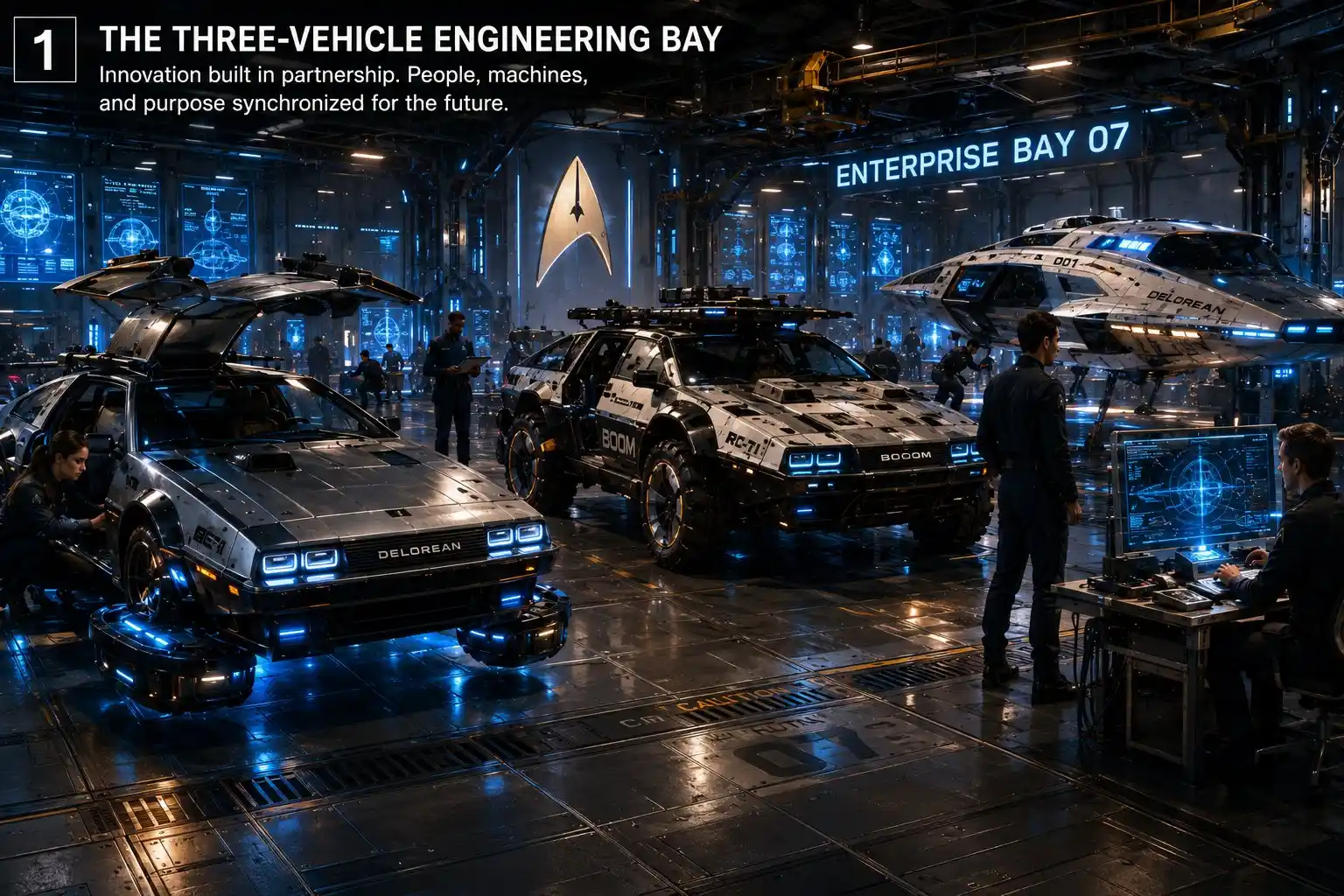
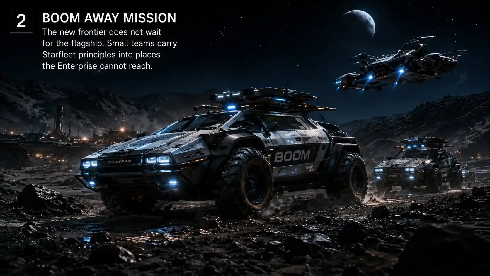
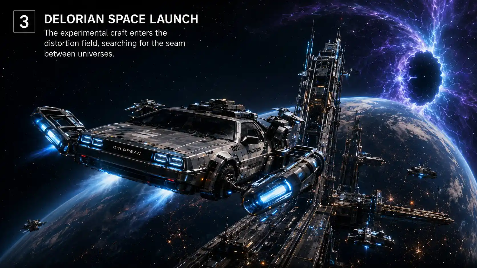
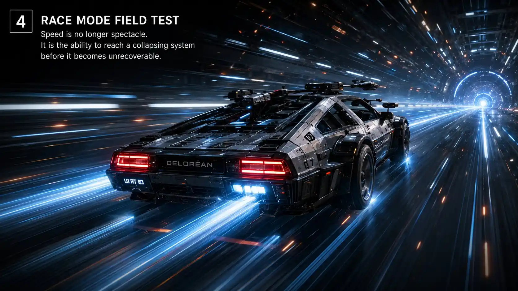
- 👉 D.E.L.O.R.I.A.N. 001 SGT-TNG – X-File 1 – Thesis + Icon
- https://x.com/SkillsGapTrain/status/2075573855167689158
- 👉 D.E.L.O.R.I.A.N. 001 SGT-TNG – X File 2 – THE FRAMEWORK
- https://x.com/SkillsGapTrain/status/2075573991566422084
- 👉 D.E.L.O.R.I.A.N. 001 SGT-TNG – X File 4 – PROOF + RED-TEAM
- https://x.com/SkillsGapTrain/status/2075574131018633350
- 👉 D.E.L.O.R.I.A.N. 001 SGT-TNG – X File 5 – Manual + Civilization
- https://x.com/SkillsGapTrain/status/2075574207409520705