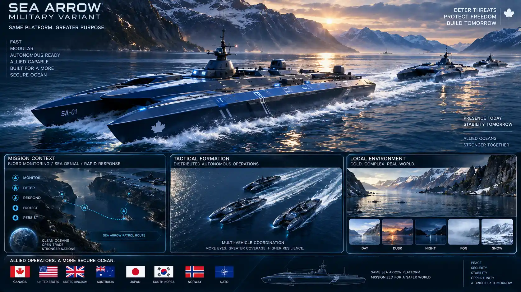
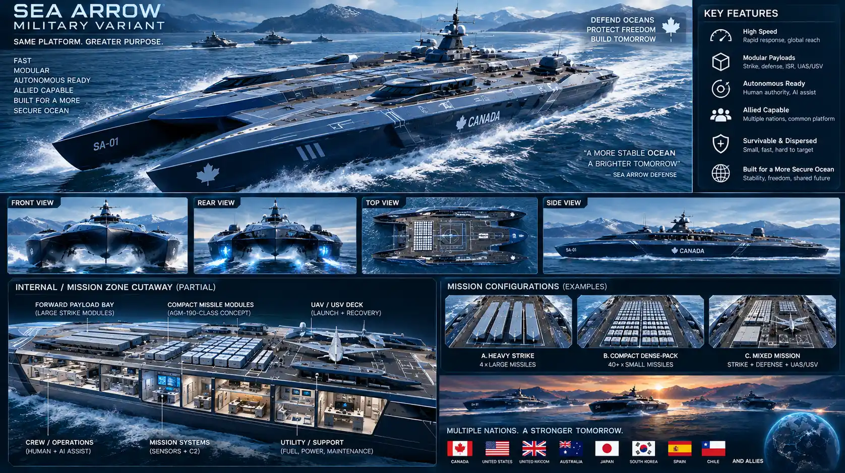
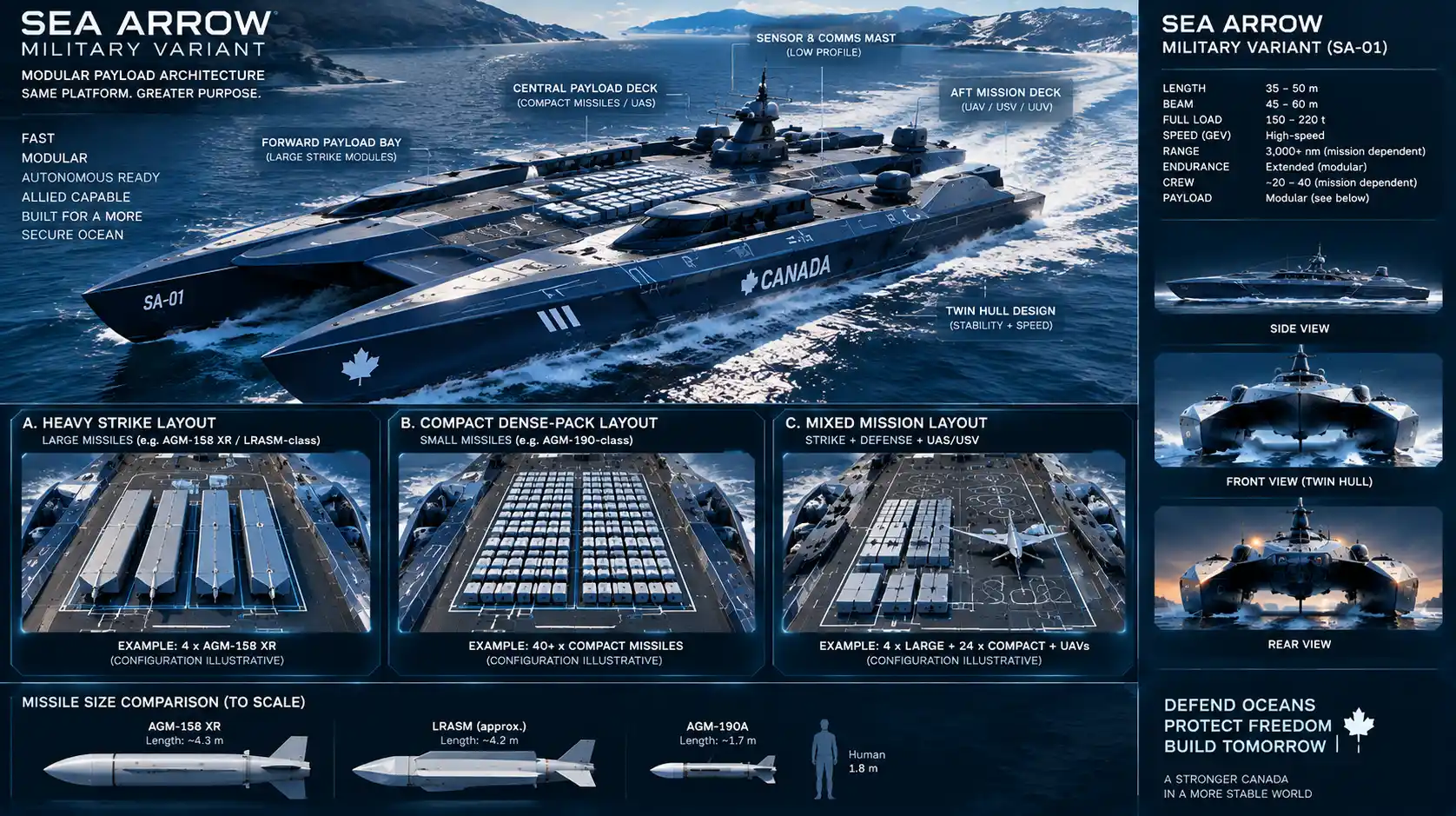
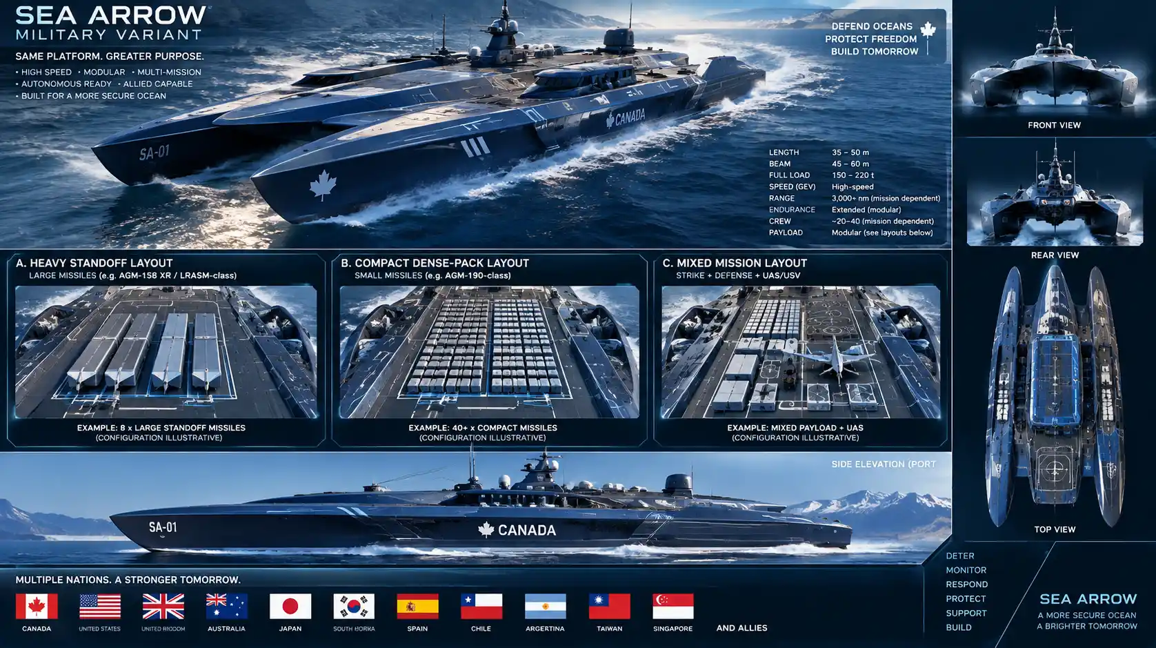
Volume II: Engineering Development & Recovery Record
SGT Disclaimer: This document contains useful engineering. Its proper purpose is:
How the Sea Arrow architecture was reconstructed, what the present engineering state is, what the numbers mean, what is open, and how the vehicle is verified.
That is where the AI-fragmentation history, provenance repair, A–M controls, A-R0/C-R0 reconstruction, evidence classes, CFD truth boundary, Appendices A–H and project records belong.
There is an important historical sentence missing from this section II:
A major reason reconstruction became necessary was that the AI-assisted development process repeatedly fragmented what had originally been conceived as an integrated system, distributing connected design reasoning across separate outputs, revisions and subsystem discussions. The recovery work was therefore partly an attempt to restore the original whole-system architecture after the tool used to assist the project had helped break that architecture into pieces.
That is the recovery history. It does not deserve to become the thesis of Sea Arrow. The actual project is about the machine. The actual problem in civilization-al engineering is the AI system itself.
The Physical Architect in the AI Age
How a 100-Knot Marine Concept Becomes a Coherent Machine
INTEGRATED DRAFT ASSEMBLY
Flagship article + technical appendices A–H + references + project records + citation-control annex
No tables. Quantitative material is expressed through prose, bullets, and controlled ASCII system maps.
Status: assembled for continuity, technical review, citation insertion.
Draft Control Note
This document assembles the Sea Arrow publication modules into one working manuscript. It is deliberately not a declaration that the vehicle is finished, built, tested, or proven. The engineering truth boundary remains the controlled project record: targets stay targets; analytical screens stay analytical screens; reconstructed CAD remains new reconstructed CAD; and the six frozen high-fidelity CFD cases remain unexecuted until real solver output exists. [P8][P10][P15][P20][P22]
The document has three layers: the ten-chapter flagship article explains the invention as a causal system; Appendices A–H open the machine up for technical readers; References and Project Records show where the external facts and internal engineering claims come from.
The central publication rule is simple: the reader should be able to see one machine at the top, deeper engineering beneath it, and traceable evidence beneath the engineering. The system map comes first. Numbers, component specifications, evidence, and audits attach to nodes on that map; they do not replace the map.
Evidence Language Used in This Draft
- CONTROLLED TARGET — required design target; not demonstrated performance.
- CONTROLLED REQUIREMENT — mission or system requirement that must eventually be verified.
- SUPPORTED — UNVALIDATED — consistent with current first-principles analysis, but higher-level evidence is still required.
- WORKING ASSUMPTION — usable for current engineering; not yet physically closed.
- BENCHMARK — current reference configuration; not automatically the final selection.
- CANDIDATE — supported option that has not been selected as final hardware or geometry.
- EXPERIMENTAL — research architecture that may fail without invalidating the practical branch.
- OPEN — no authoritative final value or selection exists.
- DIRTY — model or budget must be recalculated before authoritative reuse.
Contents
- Part I — Can This Machine Exist?
- 1. Remove the Sail
- 2. More Power Is Not Free
- Part II — How the Machine Is Discovered
- 3. Mass, Geometry and the Three-Hull Experiment
- 4. At 100 Knots, It Stops Being Just a Boat
- 5. Know What You Know
- Part III — The Sea Arrow Itself
- 6. The Complete Sea Arrow
- 7. How the Complete Machine Operates
- 8. The Sea Arrow in the Maritime Ecosystem
- Part IV — What Is Real, What Comes Next
- 9. What We Actually Designed
- 10. The Physical Architect in the AI Age
- Closing — Back to the Water
- Appendix A — Complete Vehicle Definition
- Appendix B — Mass, Payload, Fuel and Geometry
- Appendix C — Hull and High-Speed Physics
- Appendix D — Propulsion and Energy
- Appendix E — Thermal, Acoustic and Materials Architecture
- Appendix F — Sensors, Control, Autonomy and Safety
- Appendix G — Verification and Development Path
- Appendix H — Evidence, Provenance and Design History
- References
- Project Records
- Citation-Control Annex
PART I — CAN THIS MACHINE EXIST?
1. Remove the Sail
The Sea Arrow did not begin with a catalog of marine components. It began with a physical question. America’s Cup development had already shown how aggressively mass, beam, stiffness, control and fluid dynamics could be integrated when the entire craft was treated as one performance system rather than a conventional hull with equipment added afterward. The project took that high-speed multi-hull logic as inspiration, then made one deliberately disruptive move: remove the sail. [1][P2][P3]
That sounds simple until the consequences are followed honestly. The moment wind propulsion disappears, the missing propulsive function has to be replaced by machinery. Machinery has mass. It consumes fuel or stored energy. It rejects heat. It needs structure, intakes, exhausts, controls, service access and a driveline. Each of those changes displacement, center of gravity, volume, drag and failure behavior. The first design problem therefore was not ‘Which engine is best?’ It was ‘Can a mechanically propelled version of this lightweight, wide, fast multihull remain a coherent machine after the propulsion system and everything attached to it are included?’ [P3][P4][P5]
The working mission became a bundle of interacting requirements: an autonomous or uncrewed surface craft; extreme high-speed capability; useful high-speed range; approximately 1,600 kilograms of modular payload; a quieter low-speed operating personality; maintainability; and a credible path home after faults or environmental degradation. None of those requirements can be designed independently. Payload changes mass and trim. Range changes fuel. Fuel changes mass and center of gravity. Speed changes hull loading and the influence of air. Quiet operation changes propulsion, ventilation and thermal rejection. Degraded return changes redundancy and control architecture. [P4][P5]
This is why the physical architect has to think in causal order. The project eventually froze that order as a discipline, not because every real design proceeds in a perfectly straight line, but because downstream optimization becomes misleading if upstream geometry, mass or operating assumptions are still moving.
MISSION
↓
OPERATING ENVELOPE
↓
MASS / PAYLOAD
↓
GEOMETRY
↓
HYDROSTATICS
↓
HYDRODYNAMICS + AERODYNAMICS
↓
PROPULSION
↓
FUEL / RANGE
↓
CG / INERTIA / STABILITY
↓
STRUCTURE
↓
ELECTRICAL / QUIET PROPULSION
↓
THERMAL / ACOUSTIC / MATERIALS
↓
AUTONOMY / CONTROL / FAILURE
↓
MANUFACTURING / MAINTENANCE / TEST
AI is useful throughout that chain. It can recover prior work, calculate, compare alternatives, generate parametric geometry, identify contradictions and help maintain a requirement ledger. But generating more options is not the same thing as designing the system. An architecture is not the sum of the outputs. It is the controlled relationship among the mission, the physical machine, the evidence and the decisions that remain open.
The first Sea Arrow lesson therefore appears before the first engine is selected: do not begin with a preferred technology and ask the rest of the machine to absorb it. Begin with the physical system and ask what every proposed technology does to the rest of the system.
That principle would be tested immediately, because the first temptation was obvious. If the craft was supposed to be extremely fast, why not give it more power?
2. More Power Is Not Free
The early high-power branch explored four Mercury Racing 1550/1350 engines. Viewed locally, the logic was easy to understand. Four engines offered extraordinary installed power and an apparent redundancy benefit. The mistake would have been to stop the analysis at horsepower. The project did not stop there. [2][P2][P3]
An engine is not installed alone. It arrives with mass, mounting structure, drive hardware, fuel demand, exhaust, air supply, cooling, service clearances, vibration paths, wiring and controls. Four engines also change the transom structure, machinery spacing, load paths, fuel system, maintenance access and failure modes. Once those dependencies are placed on the same system map, ‘more power’ stops being a one-line improvement.
MORE ENGINES
↓
MORE ENGINE + DRIVE MASS
↓
MORE STRUCTURE
↓
MORE FUEL DEMAND
↓
MORE FUEL MASS + VOLUME
↓
MORE COOLING + VENTILATION
↓
MORE PACKAGING PRESSURE
↓
CHANGED DISPLACEMENT + CG
↓
CHANGED RESISTANCE + STABILITY
↓
CHANGED POWER REQUIRED
The contradiction is especially important on a lightweight high-speed craft. Additional machinery can force the hull to carry more mass; more mass can require more hydrodynamic support and more power; more fuel can move the center of gravity during a mission; additional cooling and ventilation can conflict with acoustic treatment; larger machinery spaces can reduce payload or service access. A component can improve while the complete vehicle becomes worse.
Redundancy has the same systems cost. Four engines may appear safer because more independent power units exist, but safety is not the same thing as component count. The better question is whether the machine can detect a fault, isolate it, reduce its operating envelope, reconfigure propulsion or control, and return safely. The architecture therefore evolved toward graceful degraded return rather than simply multiplying main engines. [P5][P8][P9]
The practical high-speed baseline became two Mercury Racing Dual Cal 1550/1350 engines. Mercury’s current product information supports the 1,550-hp and 1,350-hp calibrations and M8 drive compatibility, but the Sea Arrow selection is still a vehicle-level architecture decision whose installed performance remains unvalidated. [2][P7][P8]
At the two-engine baseline, the nominal pair provides about 2.013 MW at the 1,350-hp calibration and about 2.312 MW at 1,550 hp. Those are engine-output arithmetic, not useful propulsive power and not speed predictions. Propeller, drive, immersion, ventilation, operating attitude and the full resistance state still stand between engine rating and vehicle performance. [P7]
The four-to-two-engine reversal is one of the most useful moments in the design history because it demonstrates what a system architecture is supposed to do. The project did not choose the largest available local answer. It chose the architecture that gave the rest of the machine a chance to close.
Once propulsion stopped expanding without limit, the next problem became unavoidable: the mass had to be accounted for, located and supported by real geometry.
PART II — HOW THE MACHINE IS DISCOVERED
3. Mass, Geometry and the Three-Hull Experiment
A high-speed vehicle cannot be designed around an approximate feeling for mass. The current controlled full-load target is 12,888 kilograms. The recovered Stage-2 arithmetic consists of an 8,908-kilogram base-lightship estimate, a 900-kilogram mass-growth reserve, approximately 1,480 kilograms of fuel associated with the 2,000-liter working assumption, and a 1,600-kilogram modular payload. The arithmetic closes exactly, but the component-by-component reconstruction of the 8,908-kilogram base remains incomplete. The number is therefore a controlled target framework, not verified as-built mass. [P6][P8]
Where the mass lives matters nearly as much as how much there is. The provisional full-fuel/full-payload case places the longitudinal center of gravity at roughly 9.13 meters forward of the transom and the vertical center of gravity near 0.80 meter. Other recovered loading cases move the longitudinal center by roughly 0.41 meter across the current envelope. Those values are internally coherent enough to support the next engineering step, but an allowable high-speed CG corridor has not yet been proven. [P1][P7]
With the mass state defined well enough to continue, the hull problem became a controlled experiment rather than a styling exercise. Three geometries represented three different physical philosophies while being closed around the same displacement.
- A / Velocity — approximately 21.95 m long, 8.35 m beam, 0.55 m aft tunnel-height checkpoint and about 18° deadrise. Its design intent was the strongest sprint bias and minimum resistance, with greater concern about rough-water and pitch/aero sensitivity.
- B / Ocean — approximately 9.15 m beam, 0.75 m aft tunnel-height checkpoint and about 24° deadrise. It emphasized rough-water tolerance, reserve buoyancy and pitch damping, with a mass/drag penalty and a conditional status.
- C / Stability — approximately 8.75 m beam, 0.65 m aft tunnel-height checkpoint and about 20° deadrise. It aimed at a more balanced relationship among speed, tunnel-pressure behavior and stability. It became the benchmark, not the final hull.
All three recovered Stage-3B candidates were hydrostatically closed around 12.57365 cubic meters. At the seawater density used in the project, 1,025 kg/m³, that corresponds to 12,887.99 kilograms and independently reproduces the 12,888-kilogram full-load target. Hydrostatic arithmetic therefore agrees with the mass target. It does not tell us what the craft will do at 100 knots. [P1][P7][P16]
The CAD exercise also produced the kind of result an architect should want: it contradicted intuition. The recovered static/hydrostatic wetted areas were about 62.65 m² for A, 59.50 m² for B and 60.41 m² for C. The velocity-biased concept did not automatically have the smallest static wetted area. That did not prove B would be fastest; it proved that a verbal label such as ‘Velocity’ is not a substitute for geometry. [P3][P16]
A later source-recovery pass then exposed another important boundary. The project record strongly supports that the historical A/B/C Stage-3B CAD solids existed, but the actual source surfaces were not recovered in the accessible evidence. The correct response was not to pretend that generated illustrations were the CAD. It was to reconstruct new controlled geometry from the recovered constraints and label it as new analysis. [P16]
That process produced A-R0 and C-R0. A-R0 closes to 12.569650 m³, a static wetted area of 62.623597 m² and an LCB of 9.126440 m. C-R0 closes to 12.572347 m³, 60.414357 m² and an LCB of 9.129270 m. Both are watertight and CFD-frozen as G2 reconstructed geometry. Their LCBs were deliberately fitted close to the 9.13-m LC-01 LCG as a new reconstruction objective; that balance is not retroactively attributed to the historical CAD. [P17]
By keeping A and C alive for comparative analysis, the project avoids another common failure: selecting the favorite geometry before the regime that matters has been simulated. At low speed, the craft is recognizably a catamaran. At 100 knots, the problem changes.
4. At 100 Knots, It Stops Being Just a Boat
One hundred knots is about 51.44 meters per second. At that speed, the length Froude number for the 21.95-meter craft is approximately 3.51. The water dynamic-pressure scale is about 1.36 MPa; the air dynamic-pressure scale is only about 1.62 kPa, but air acts over large exposed areas and can create moments through long lever arms. The machine has approximately 17.05 MJ of translational kinetic energy at the 12,888-kilogram controlled mass. These are analytical screens, not test results. [P7]
The point of those numbers is not drama. It is regime identification. Ordinary displacement reasoning cannot be extrapolated into this region. The hull must become dynamically supported, the running wetted area must collapse relative to the static hydrostatic state, the tunnel becomes an aerodynamic and pressure-management problem, and pitch stability becomes coupled to both water and air. Foundational planing-hull work helps explain why lift, trim, wetted area and center of pressure interact, but the Sea Arrow’s tunnel-cat behavior at 100 knots requires its own high-fidelity analysis. [4][5][P7]
A power-based screen shows the constraint sharply. With the two 1,550-hp engines and an assumed 55–75 percent overall engine-to-useful-thrust efficiency band, the total steady-state drag compatible with 100 knots is roughly 24.7–33.7 kN. That is not a prediction of actual drag; it is a boundary generated from available power. [P7]
Now compare that boundary with the wrong running state. If the C benchmark carried its roughly 60.41 m² static/hydrostatic wetted area into 100-knot operation, a friction-only diagnostic is on the order of 125 kN. For A-R0, the corresponding static-area diagnostic is about 129.6 kN. Those diagnostics omit pressure drag, spray, appendage and aerodynamic losses, so they cannot be running-drag predictions. Their purpose is to show that the static area cannot survive as the high-speed running state. Dynamic unloading is not optional. [P20][P23]
The same screen can be inverted. If the entire 100-knot drag allowance were consumed only by turbulent skin friction, the equivalent wetted area would be on the order of 11.9–16.3 m² before the other drag mechanisms were added. Again, that is not a design specification. It is a diagnostic that tells the architect what the future CFD result must broadly reconcile: the water-contact state at high speed has to be radically different from the static state. [7][P7]
The air side cannot be ignored simply because air is less dense than water. Aerodynamic lift or drag generated away from the center of gravity creates pitch moment. Tunnel pressure can move the effective support center. A small change in trim can change water contact, propulsor immersion, spray, ventilation and aerodynamic loading at the same time. That creates the possibility of coupled instabilities such as porpoising or an excessive pitch-up tendency. No quantitative blowover or porpoising margin is claimed in this draft. Those margins are open engineering work. [P7][P9]
This is exactly why the next evidence gate is narrow. The first comparative campaign contains six cases only: A-R0 and C-R0, each at 60, 80 and 100 knots, in the same LC-01 mass state with heave and pitch free. Required outputs include resistance, trim, heave, pitch moment, dynamic wetted area, tunnel pressure, pressure distribution, support center, spray and ventilation behavior, propulsor-inflow observations, convergence histories and numerical uncertainty. [P17][P20][P21][P24]
Those cases are configured but have not been executed. The available runtime did not contain the qualified high-fidelity transient two-phase solver required to produce a defensible V2 result. No result was invented. [P20][P22]
At this point the architect has done enough analytical work to know what has to be measured by the next model. That is also the right point to stop claiming knowledge.
5. Know What You Know
Engineering becomes dangerous when different evidence levels are allowed to blur together. A recovered historical statement is not the same thing as a new calculation. A CAD solid is not the same thing as a sea trial. A target is not a demonstration. A plausible component family is not final installed hardware. The Sea Arrow recovery therefore turned evidence status into part of the design itself. [P2][P8][P10]
The project now distinguishes recovered evidence, derived arithmetic, new analysis, working assumptions, candidates, benchmarks, experimental branches and open items. That vocabulary is not administrative decoration. It prevents a polished report from becoming more authoritative than the physics it is supposed to describe.
The geometry story is the clearest example. There is strong evidence that the historical A/B/C CAD solids existed and closed hydrostatically. The actual source surfaces are unavailable. A-R0 and C-R0 therefore cannot be called recovered originals; they are new, controlled reconstructions created from recovered constraints. The distinction remains visible even though the reconstructions reproduce the important volume and wetted-area checkpoints extremely closely. [P16][P17]
The CFD story is equally important. A solver-ready six-case campaign exists. Inputs, domain, motion model, mesh/time-step starting strategy, numerical-verification requirements and output schema exist. What does not exist is the V2 flow solution. The manuscript can explain why the craft appears analytically plausible and what the simulation must test, but it cannot say that the simulation has confirmed the design. [6][8][P20][P21][P22]
The same discipline applies to the performance headline. One hundred knots remains a controlled minimum engineering target. One hundred twenty knots is a stretch target. One hundred thirty knots and above remains a research region. The 300-nautical-mile efficient-high-speed range is a hard requirement, not a demonstrated mission radius. The current fuel quantity is a working assumption. The final propeller and M8 ratio are open. [P8][P10][P15]
Uncertainty is therefore not something to hide until a later report. It is information. It tells the architect which part of the machine is authoritative, which part is provisional, which part is experimental, and what evidence is required next.
This matters even more in an AI-assisted process because AI can produce convincing continuity where the evidence actually contains gaps. It can write a smooth answer to an unsolved problem. The physical architect has to be able to say: this is the number we recovered; this is the assumption we made; this is what the calculation indicates; this is what the simulation has not yet told us.
With that boundary protected, the publication can finally do what a reader needs: stop watching the project search for the machine and show the proposed machine itself.
PART III — THE SEA ARROW ITSELF
6. The Complete Sea Arrow
The current Sea Arrow is a proposed autonomous high-speed tunnel catamaran approximately 21.95 meters long, organized around a controlled full-load target of 12,888 kilograms, twin Mercury Racing 1550/1350 main engines, a 1,600-kilogram modular payload allowance and separate low-speed quiet-propulsion branches. C / Stability remains the geometry benchmark and A / Velocity remains the principal dynamic comparison; no final hull is frozen. [2][P8][P10][P16]
The vehicle is best understood as one connected architecture rather than a list of technologies. The hull and tunnel establish buoyancy, running surface, air/water interaction and machinery volume. The main engines create high-speed propulsion but also fuel demand, heat, vibration, exhaust and structural loads. Fuel changes range and center of gravity. Payload changes mass, trim and structural hardpoints. Quiet operation requires a propulsion path that does not depend on keeping the large gasoline engines running. Thermal control has to remove heat without defeating acoustic isolation. Materials have to carry load and move heat while surviving saltwater and mixed-material galvanic interfaces. Sensors and control have to know enough about the machine to keep it within a safe operating envelope. [P5][P8]
MISSION / OPERATING MODE
│
▼
MASS + GEOMETRY
┌────┴─────┐
▼ ▼
HULL/TUNNEL CG/INERTIA
│ │
└────┬─────┘
▼
HYDRO + AERO + STABILITY
│
▼
2 × MERCURY MAIN PROPULSION
┌────┼───────────┐
▼ ▼ ▼
FUEL HEAT VIBRATION
│ │ │
▼ ▼ ▼
RANGE THERMAL ACOUSTIC
│ │
└────┬──────┘
▼
MATERIALS / PACKAGING
│
┌──────┴─────────┐
▼ ▼
P1 ELECTRIC P2 EXPERIMENTAL
QUIET DRIVE MHD AUXILIARY
│ │
└──────┬─────────┘
▼
SENSORS → REAL-TIME CONTROL
│
MISSION AUTONOMY + SAFETY GOVERNOR
│
DEGRADED RETURN
The high-speed propulsion path is common to both P1 and P2. Two Mercury Racing Dual Cal 1550/1350 engines remain the selected main-engine architecture. The M8 family is a manufacturer-supported candidate, but the final ratio and propeller are open because the high-speed running attitude, propulsor inflow, ventilation behavior and resistance state are not yet closed. [2][3][P7][P8]
P1 is the practical prototype path. In quiet operation the Mercury mains are shut down where practical and a separate electric low-speed propulsion system carries the craft. The architecture is selected, but battery chemistry, usable capacity, voltage, inverter, motor/propulsor hardware, quiet endurance and emergency-return energy remain open. The analytical examples in the project are sizing screens, not final hardware specifications. [P8][P10]
P2 keeps the same high-speed core and substitutes an experimental MHD auxiliary path for the practical quiet propulsors. MHD seawater propulsion is real physics and was demonstrated by the YAMATO1 program, but that does not make it a closed Sea Arrow subsystem. Electrical efficiency, magnet mass, Joule heating, electrochemistry, bubbles, magnetic signature, corrosion and net acoustic/signature benefit all remain research questions. [16][17][P8]
The thermal architecture is organized around the sequence spread, buffer, distribute, cool, reject. The conceptual path uses high-conductivity spreading material near intense electronics, lightweight protected metallic distribution where appropriate, liquid coolant and corrosion-resistant seawater heat rejection. Pyrolytic graphite is physically attractive as a local spreader because of its strong in-plane thermal conductivity, but no commercial sheet is selected. Titanium is a plausible wet-interface/heat-exchanger material because of its seawater corrosion performance; final alloy, thickness and heat-exchanger geometry remain open. [12][13][14][P5][P8]
The materials architecture similarly treats compatibility as a system. CFRP is the primary structural logic. GFRP is used conceptually to isolate conductive interfaces. Protected aluminum may serve lightweight internal/thermal functions where galvanic control is credible. Titanium is reserved for corrosion-critical wet interfaces. Carbon/aluminum galvanic coupling in chloride environments is a known risk, so isolation, coatings, drainage, inspection and test have to be part of the joint architecture rather than afterthoughts. [9][10][11][P5]
The control system is separated into layers. Real-time vehicle control handles the fast physical loops: pitch, roll, yaw, thrust, steering and trim. Mission autonomy handles navigation and mission behavior within limits. An independent safety governor constrains or vetoes unsafe operation. Remote human supervision remains supervisory rather than pretending a distant communications link can replace local high-speed stability control. [P5][P9][P10]
The result is not a finished production craft. It is a coherent proposed machine with a controlled relationship among hull, propulsion, energy, thermal management, materials, control and failure behavior. The next question is what that complete machine actually does when it moves through its operating modes.
7. How the Complete Machine Operates
The best way to understand the architecture is to follow the machine through a representative operating sequence. The following sequence is illustrative; it is not a claim that a prototype has performed the mission.
At departure, the craft is in a low-energy, low-speed state. The main gasoline engines can remain off where practical. P1 uses its electric auxiliary propulsion for maneuvering; P2 would use its experimental MHD branch only if that branch eventually proves viable. Navigation, vehicle-state sensors, local control and the safety governor are active. The point is not absolute silence. It is to remove the largest combustion, exhaust and high-power mechanical sources from the operating state when speed is not required. [P8][P10]
As the craft leaves the constrained area and speed becomes more important, the main propulsion path comes online. The operating personality changes. Fuel flow rises, cooling demand rises, vibration paths become active, ventilation and exhaust matter, and the acoustic architecture changes from quiet-mode source suppression toward damage-free operation of a powerful mechanical system. The transition has to be managed as a system state, not as a simple throttle command. [P5]
During high-speed repositioning, control becomes local and fast. At 100 knots the vehicle travels about 5.14 meters in one tenth of a second and about 25.72 meters in half a second. A remote human link cannot close the primary pitch-stability loop at that timescale. Local deterministic vehicle control therefore operates beneath higher-level mission autonomy, while the independent governor enforces the validated envelope. [P7][P10]
The hull is also operating in a different physical state. Static wetted area is no longer the relevant support picture. Dynamic water contact, tunnel pressure, aerodynamic loading, trim and propulsor immersion are interacting. The control system cannot compensate for physics that the geometry cannot support; the CFD and later test program must first establish where stable operating states actually exist.
Now introduce a fault. It could be propulsion, cooling, electrical, navigation, sensor disagreement or communications loss. The machine should not continue attempting the original mission as though nothing changed. The failure doctrine is: detect the problem, isolate it, shed nonessential loads, reconfigure what remains, reduce the permitted operating envelope, and then continue, return or enter a safe state. [P5][P9]
FAILURE
↓
DETECT
↓
ISOLATE
↓
SHED NONESSENTIAL LOAD
↓
RECONFIGURE
↓
REDUCE SPEED / SEA-STATE ENVELOPE
↓
CONTINUE | RETURN | SAFE STATE
A one-engine condition illustrates why this doctrine is more useful than simply counting engines. The remaining engine may be capable of propelling the craft, but that does not prove that the original high-speed stability, cooling, steering or propulsor-immersion margins remain valid. The degraded-control law therefore has to move the vehicle into a separately verified region rather than assume symmetry where symmetry no longer exists. [P9]
Communications loss is treated similarly. Mission autonomy may continue only within pre-authorized bounds. The local safety governor does not disappear because the remote link disappears. Navigation degradation requires cross-checking sensors and reducing the envelope when the vehicle’s state estimate becomes less trustworthy. Contemporary maritime-autonomy work is moving in the same general direction: defined operating modes, operating limits, risk assessment and explicit human oversight rather than one undifferentiated concept of ‘autonomy.’ [15]
The operational sequence reveals why the complete architecture matters. Quiet propulsion is not an isolated gadget; it changes thermal and acoustic states. High-speed propulsion is not just horsepower; it changes stability and control. A fault is not only a component failure; it changes the permitted mission and physical envelope. The craft works only if the architecture understands those relationships before the water forces them on the prototype.
8. The Sea Arrow in the Maritime Ecosystem
A fast autonomous surface craft becomes more useful when it is treated as a node inside a larger maritime system rather than as an isolated speed record. The Sea Arrow concept is therefore best described by the functions it could support if the vehicle is eventually validated: rapid movement of modular sensors or payloads, distributed maritime observation, communications relay, mapping and environmental data collection, inspection support, search-and-rescue assistance, and other missions where a small surface node benefits from speed, endurance, autonomy and a reduced-signature low-speed mode. [P4][P5]
That system can contain human command nodes, shore stations, satellites, crewed ships, aircraft, unmanned air vehicles, underwater vehicles and other surface systems. Sea Arrow does not have to own every sensor or make every decision. Its architectural value is the ability to move, sense, communicate and return while staying inside its own safe physical envelope.
The distinction between local vehicle control and mission-level command becomes even more important in a network. The craft may receive a destination, search area or payload task from an external node, but the external node should not be responsible for millisecond-scale pitch stability or actuator protection. Conversely, the local controller should not turn a bounded vehicle-control function into authority over broader mission objectives. That separation keeps control latency, safety and human command understandable. [P5][P10]
The quiet operating mode creates another ecosystem role. A craft does not need to be absolutely acoustically invisible to benefit from shutting down major combustion machinery during low-speed observation, approach, loiter or harbor movement. The design question is whether the quieter propulsion path, thermal rejection, hotel loads and endurance can be closed without consuming the mass and volume that the high-speed machine needs. P1 is the practical route to answering that question. P2 is deliberately allowed to fail as research without destroying P1. [P8][P10]
The high-speed mode offers a different value proposition: time. Speed can shorten the interval between dispersed points, move a sensor or payload rapidly, respond to an emergency or reposition the vehicle before conditions change. But the architecture refuses to treat speed as free utility. Every high-speed mission is constrained by range, sea state, vehicle loading, validated stability and the energy state available for the return leg.
That makes the Sea Arrow ecosystem concept different from a simple ‘fast autonomous boat’ description. The machine is defined by its operating personalities and by the rules that govern transitions among them. Quiet mode, transit, high-speed operation, degraded return and safe state are different configurations of the same physical system.
The larger lesson is that platform value emerges from interfaces. A vehicle becomes useful to a wider system when its power, data, payload, navigation, maintenance, command and failure boundaries are explicit enough that other nodes can rely on it. The platform therefore earns its place in the ecosystem by being understandable, not by pretending to be universally autonomous.
That brings the manuscript to the final distinction: what has actually been designed, and what still belongs to the future evidence program.
PART IV — WHAT IS REAL, WHAT COMES NEXT
9. What We Actually Designed
The project has moved well beyond a loose visual concept, but it has not crossed into demonstrated vehicle performance. The useful description is therefore neither ‘just an idea’ nor ‘a finished 100-knot craft.’ It is a controlled system architecture with closed and open evidence states.
The following elements are genuinely present in the current engineering record:
- A recovered design lineage from America’s Cup-inspired multihull thinking, through removal of the sail, four-engine exploration, the systems reversal to two engines, mass/CG work, three hull philosophies, hydrostatic closure, the high-speed aero-hydrodynamic problem, and the P1/P2 quiet-propulsion branches. [P2][P3]
- A controlled mass framework: 12,888 kg full-load target, 8,908 kg provisional base lightship, 900 kg mass-growth reserve, approximately 1,480 kg fuel and 1,600 kg payload. [P6][P8]
- Recovered A / Velocity, B / Ocean and C / Stability geometry constraints and hydrostatic checkpoints. [P16]
- New watertight A-R0 and C-R0 parametric CAD reconstructions that reproduce the important Stage-3B hydrostatic checkpoints closely and are frozen as the first comparative CFD geometries. [P17][P18]
- First-principles analytical screens for speed regime, dynamic pressure, kinetic energy, power/drag boundary, effective wetted area, range, P1 propulsion, MHD energy loss, thermal scale and control latency. [P7]
- A complete system and interface architecture connecting mass, geometry, propulsion, fuel, thermal, acoustic, materials, sensors, control, autonomy, safety and degraded return. [P5][P10]
- A V0–V7 verification ladder and a staged development program from analytical work through simulation, component/subsystem test, prototype test, instrumented sea trial and operational evidence. [P9]
- A frozen six-case Stage 4B-1 CFD campaign with controlled geometry, mass properties, domain, motion assumptions, solver requirements, output schema and numerical-verification requirements. [P19][P20][P21][P24]
The following items are specifically not demonstrated:
- 100-knot vehicle performance.
- 120-knot stretch performance or the 130+ knot research region.
- 300-nautical-mile efficient-high-speed range.
- The final high-speed hull.
- The final propeller or M8 ratio.
- Dynamic trim, running wetted area, tunnel-pressure distribution or high-speed support-center behavior.
- Quantitative porpoising, blowover or full 6-DOF stability margins.
- Final structural laminate design and FEA closure.
- Final P1 battery, inverter, motor or auxiliary propulsor.
- A proven net signature advantage for P2 MHD.
- Full thermal and acoustic closure.
- Prototype sea-trial evidence.
The current CFD state is particularly important. All six initial cases are configured; none has been physically executed in a qualified solver environment. The pre-CFD friction diagnostics are intentionally conservative screens using static/hydrostatic area and must never be relabeled as running drag. [P20][P22][P23]
The correct next new evidence is therefore not another architecture essay. It is the six transient two-phase A-R0/C-R0 simulations at 60, 80 and 100 knots, with heave and pitch free and numerical uncertainty quantified. No 120/130-knot expansion, propeller optimization, battery selection, thermal redesign or MHD development should outrun that geometry-and-dynamics gate. [P20][P21]
That narrowness is a sign of progress. The project has reached a stage where the next answer should come from the model of the water and air, not from adding more conceptual detail.
10. The Physical Architect in the AI Age
The Sea Arrow project is also an experiment in how engineering work changes when AI can generate, search, calculate, reconstruct, compare and write at enormous speed. The obvious benefit is productivity. The less obvious risk is that productivity can create the appearance of closure faster than physics can create evidence.
AI was useful in the project for recovering lost structure from scattered records, separating branches, checking arithmetic, maintaining a requirements ledger, generating alternative system maps, producing new parametric CAD, building a solver-ready CFD campaign, identifying inconsistent wording and exposing the places where a report had become more confident than the evidence. Those are real capabilities. [P2][P7][P16][P17][P20]
But the machine did not become coherent because AI produced more text. It became more coherent when the architecture repeatedly forced outputs back onto the same physical map. An engine had to connect to fuel, heat, structure and CG. A hull had to connect to displacement, dynamic support and propulsor inflow. Quiet propulsion had to connect to battery, thermal rejection and acoustic goals. Autonomy had to connect to control latency and a separate safety authority.
The physical architect’s role is therefore not to compete with AI at generating alternatives. It is to preserve the questions that computation cannot answer by eloquence. Which requirement is authoritative? Which geometry is the current source? What changed? What is the evidence level? Which subsystem becomes dirty if this assumption moves? What test would falsify this claim? When should the work stop and wait for a solver, a component or the water?
That last question is especially important. The Stage 4B-1 campaign was configured, but the required solver was not installed in the working environment. The correct engineering act was not to approximate a CFD result with attractive numbers. It was to freeze the configuration and mark the result unavailable. [P20][P22]
AI can assist the architect, but it should not become the authority that upgrades a target into a fact. The authority chain remains human and evidentiary: mission and requirements are set by legitimate human decision; models and tools produce evidence; engineers interpret that evidence; configuration control records what changed; tests decide whether the physical machine behaves as predicted.
This is the deeper reason to keep the entire Sea Arrow comprehensible. When a system becomes so fragmented that no person can see the relationships among propulsion, fuel, geometry, heat, control and failure, AI can make the fragmentation look organized without actually restoring understanding. The physical architect does the opposite. The architect keeps a system small enough, explicit enough and causal enough that specialists, tools and evidence can attach to one common model of the machine.
The goal is not to remove imagination from engineering. It is to give imagination a disciplined path into matter. The visionary question creates the project. AI expands the search space. Architecture turns the search into relationships. Physics removes impossible branches. Evidence changes status. Testing earns the right to claim performance.
Sea Arrow is therefore valuable even before the prototype exists. It is a worked example of a design culture for the AI age: imaginative enough to ask a difficult question, technical enough to expose every consequence, and disciplined enough to stop when the next answer belongs to reality.
Closing — Back to the Water
The project began by removing a sail from a high-speed multihull idea and asking what the rest of the machine would have to become. That question led through too much power, mass reversal, three hull philosophies, a CAD surprise, the 100-knot water/air transition, quiet propulsion, thermal and acoustic coupling, materials compatibility, layered autonomy and degraded return.
The architecture now exists. The controlled mass model exists. Two new CFD-ready comparison geometries exist. The six-case campaign exists. The evidence boundary exists.
What does not yet exist is the answer that matters next.
That answer is in the water.
APPENDIX A — COMPLETE VEHICLE DEFINITION
Purpose: answer one question — What is the vehicle? The entries below define the current proposed architecture without converting open engineering into finished specifications.
A.1 Mission and Operating Concept
- Autonomous / uncrewed high-speed surface platform.
- Controlled minimum speed target: ≥100 kt; 120 kt stretch; 130+ kt research region.
- Efficient-high-speed range requirement: ≥300 nmi, with mission reserve logic retained but exact implementation open.
- Modular payload target: 1,600 kg.
- Controlled mission sea-state anchor: Hs≈1.25 m.
- Degraded/survival-return anchor: Hs≈2.5 m; this is not a speed rating.
- Separate low-speed quieter operating personality.
- Graceful degraded return after relevant faults.
A.2 Principal Dimensions and Status
- Length overall: approximately 21.95 m / 72 ft.
- Architecture: twin-hull / central-tunnel catamaran.
- Controlled full-load target: 12,888 kg.
- Hydrostatic target volume: 12.57365 m³ at the project’s 1,025 kg/m³ seawater assumption.
- Current geometry status: C / Stability = benchmark; A / Velocity = comparison; B / Ocean = conditional/reference.
- Final production hull: OPEN.
A.3 Full-Load Configuration
- Base lightship excluding reserve: 8,908 kg — provisional recovered estimate.
- Growth reserve: 900 kg — mass reserve only.
- Fuel: approximately 1,480 kg associated with the 2,000 L working assumption.
- Modular payload: 1,600 kg.
- Full-load arithmetic total: 12,888 kg.
- Full-load LCG: approximately 9.13 m forward of transom — provisional.
- Full-load VCG: approximately 0.80 m — provisional.
A.4 Major Arrangement
- Two longitudinal hulls separated by a central tunnel.
- Twin Mercury Racing 1550/1350 main propulsion architecture.
- Fuel located to manage range and CG migration; final tank geometry remains open.
- Modular payload installed near the vehicle CG where practical to reduce trim/stability disturbance.
- P1: separate practical electric low-speed / quiet propulsion.
- P2: experimental MHD low-speed branch; does not replace the twin Mercury high-speed core.
- CFRP primary structural logic with mixed-material isolation and corrosion control.
- Distributed sensor, navigation, control, safety, electrical, thermal and communications systems.
A.5 Operating Modes
- M0 — Safe / secured / maintenance state.
- M1 — Quiet low-speed operation; Mercury mains off where practical.
- M2 — Normal transit.
- M3 — High-speed operation inside validated envelope.
- M4 — Sprint / maximum-performance state, only after validation supports it.
- M5 — One-main-engine / propulsion-degraded return.
- M6 — Navigation and/or communications degraded state.
A.6 Master System Architecture
MISSION
│
├─ speed / range / payload / sea state / quiet mode
│
▼
MASS + GEOMETRY
│
├─ hull + tunnel
├─ CG + inertia
└─ payload + fuel
│
▼
AERO-HYDRO + STABILITY
│
▼
MAIN PROPULSION
├─ fuel → range
├─ heat → thermal
├─ vibration → acoustic
└─ loads → structure
│
▼
P1 / P2 QUIET PROPULSION
│
▼
SENSORS + REAL-TIME CONTROL
│
MISSION AUTONOMY
│
INDEPENDENT SAFETY GOVERNOR
│
DEGRADED RETURN
A.7 Complete Vehicle Cutaway / System Plate — Draft Callout Set
- Twin hulls and central tunnel.
- Main engine positions and M8 candidate driveline region.
- Fuel volume / tank zones and CG reference.
- Payload module region near CG.
- P1 quiet-propulsion hardware zone or P2 MHD experimental zone.
- Primary electrical distribution and energy storage.
- Thermal spreaders, coolant path and seawater heat rejection.
- Acoustic isolation zones and ventilation paths.
- Navigation and vehicle-state sensors.
- Real-time control, mission-autonomy compute and independent safety governor.
- Service access, replaceable modules and degraded-return pathways.
APPENDIX B — MASS, PAYLOAD, FUEL AND GEOMETRY
B.1 Mass Budget
- 8,908 kg — base lightship excluding growth reserve; recovered but component ledger remains incomplete.
- 900 kg — growth reserve; may not be treated as free discretionary mass.
- 9,808 kg — lightship including reserve.
- 1,480 kg — fuel working mass.
- 1,600 kg — modular payload target.
- 12,888 kg — controlled full-load target; arithmetic closes.
B.2 Fuel Assumption
- Working volume: 2,000 L.
- Working mass: 1,480 kg.
- Implied density: approximately 0.740 kg/L; consistency result only.
- The ~15% reserve belongs to mission range-reserve logic; it is not automatically a permanent fixed fuel holdback.
- Tank geometry, venting, pickup, baffling and final fuel grade remain engineering work.
B.3 Payload Allowance
- Target payload: 1,600 kg, approximately one-eighth of full-load mass.
- Payload location is a first-order trim/stability variable.
- Preferred location is near CG where practical.
- Final hardpoints, payload envelope and service interfaces remain open.
B.4 Growth Reserve
- 900 kg is retained as mass-growth reserve only.
- It is not electrical-energy reserve, thermal margin or range reserve.
- Incomplete subsystem mass reconstruction can consume it rapidly.
B.5 LCG / VCG
- Full fuel / full payload: ~12.888 t; LCG ~9.13 m; VCG ~0.80 m.
- Full fuel / no payload: ~11.288 t; LCG ~8.86 m.
- 15%-fuel load case / full payload: ~11.63 t; LCG ~9.03 m.
- 15%-fuel load case / no payload: ~10.03 t; LCG ~8.72 m.
- Approximate recovered longitudinal migration: ~0.41 m, about 1.9% LOA.
- Allowable dynamic CG corridor: OPEN.
B.6 Fuel and Payload Loading Cases
- LC-01 — full fuel / full payload.
- LC-02 — full fuel / no payload.
- LC-03 — 15%-fuel load case / full payload.
- LC-04 — 15%-fuel load case / no payload.
B.7 Inertia Model
- Ixx ≈ 1.11 × 10^5 kg·m².
- Iyy ≈ 2.82 × 10^5 kg·m².
- Izz ≈ 3.84 × 10^5 kg·m².
- Status: provisional controlled inputs; recompute from the mature component mass model before final dynamic validation.
B.8 A / B / C Geometry Summary
- A / Velocity — beam 8.35 m; aft tunnel 0.55 m; deadrise ~18°; recovered static wetted area ~62.65 m²; sprint-biased comparison.
- B / Ocean — beam 9.15 m; aft tunnel 0.75 m; deadrise ~24°; recovered static wetted area ~59.50 m²; conditional/reference rough-water philosophy.
- C / Stability — beam 8.75 m; aft tunnel 0.65 m; deadrise ~20°; recovered static wetted area ~60.41 m²; current benchmark, not final hull.
APPENDIX C — HULL AND HIGH-SPEED PHYSICS
C.1 A / Velocity
- Purpose: strongest sprint bias / resistance minimization philosophy.
- Recovered geometry: 21.95 m length, 8.35 m beam, 0.55 m aft tunnel checkpoint, ~18° deadrise.
- Recovered Stage-3B static/hydrostatic wetted area: ~62.65 m².
- Risk emphasis: rough-water sensitivity and pitch/aero sensitivity.
- Current status: valid dynamic CFD comparison; original source surface unrecovered.
C.2 B / Ocean
- Purpose: rough-water tolerance, reserve buoyancy and pitch damping.
- Recovered geometry: 9.15 m beam, 0.75 m aft tunnel checkpoint, ~24° deadrise.
- Recovered static/hydrostatic wetted area: ~59.50 m².
- Recovered status: conditional, including an approximately 70-kg correction noted in the historical record.
- Not in the first six-case CFD campaign by default.
C.3 C / Stability
- Purpose: balanced speed/stability philosophy and controlled tunnel-pressure release.
- Recovered geometry: 8.75 m beam, 0.65 m aft tunnel checkpoint, ~20° deadrise.
- Recovered static/hydrostatic wetted area: ~60.41 m².
- Current status: benchmark / leader, not final hull.
C.4 Hydrostatic Closure
- Recovered target displacement volume: 12.57365 m³.
- Using 1,025 kg/m³ seawater: 12,887.99 kg.
- This reproduces the controlled 12,888-kg full-load target.
- Hydrostatic closure does not validate running trim, resistance, stability, structure or range.
C.5 Static Wetted Area
The recovered Stage-3B areas are static/hydrostatic values. They are not 100-knot running areas. Their most important historical value is that they challenged the intuitive assumption that the velocity-biased hull must automatically have the lowest static wetted area.
C.6 A-R0 and C-R0 Reconstructed CAD
- A-R0: displaced volume 12.569650 m³; error −0.0318%; static wetted area 62.623597 m²; error −0.0421%; LCB 9.126440 m; watertight; valid B-rep.
- C-R0: displaced volume 12.572347 m³; error −0.0104%; static wetted area 60.414357 m²; error +0.0072%; LCB 9.129270 m; watertight; valid B-rep.
- Both: G2 — NEW RECONSTRUCTED CAD / NEW ANALYSIS; CFD-frozen for the first comparison.
- Neither: recovered original Stage-3B surface or final hull.
C.7 Dynamic Unloading
- At 100 kt, static-area friction-only diagnostics are ~129.6 kN for A-R0 and ~125.0 kN for C-R0.
- Current power-based total-drag screen at 100 kt is ~24.7–33.7 kN.
- Therefore the static/hydrostatic water-contact state cannot persist to 100 kt.
- A friction-only effective-wetted-area screen gives ~11.9–16.3 m² at 100 kt before other drag sources.
- This is a diagnostic envelope, not an exact required running area.
C.8 Aero-Hydrodynamic Coupling
- 100 kt ≈ 51.44 m/s; Fn≈3.51.
- Water dynamic-pressure scale ≈1.36 MPa.
- Air dynamic-pressure scale ≈1.62 kPa.
- Air remains first-order because force acts across large surfaces and creates pitch moment through lever arms.
- Tunnel pressure, trim, aerodynamic center, hydrodynamic support center, running wetted area and propulsor immersion must be solved together.
- Porpoising and blowover margins are OPEN.
C.9 Power / Drag Screens
- 2×1350 hp ≈2.013 MW nominal mechanical output.
- 2×1550 hp ≈2.312 MW nominal mechanical output.
- At 100 kt with the Gate-F 55–75% useful-thrust efficiency screen: total-drag ceiling ≈24.7–33.7 kN.
- These are acceptance screens, not CFD or sea-trial results.
C.10 Six-Case CFD Campaign
- A-R0 / LC-01 / 60 kt.
- A-R0 / LC-01 / 80 kt.
- A-R0 / LC-01 / 100 kt.
- C-R0 / LC-01 / 60 kt.
- C-R0 / LC-01 / 80 kt.
- C-R0 / LC-01 / 100 kt.
Required evidence: total resistance, heave, trim, pitch moment, dynamic wetted area, pressure, tunnel pressure, free surface and spray, vertical support, support center, propulsor inflow, ventilation observations, force/moment histories, convergence and numerical uncertainty. Status: CONFIGURED, NOT EXECUTED. [P20][P21][P22]
APPENDIX D — PROPULSION AND ENERGY
D.1 Twin Mercury 1550/1350 Main Architecture
- Selected main architecture: 2 × Mercury Racing Dual Cal 1550/1350.
- Current manufacturer ratings: 1,550 hp / 1,350 hp at the transom.
- Nominal pair mechanical output: ~2.312 MW / ~2.013 MW.
- Main engines serve transit/high-speed/sprint modes; they are not the quiet-mode propulsion source.
D.2 Drive-System Status
- M8 family: manufacturer-supported candidate.
- Dedicated M8 page ratios: 1.69:1, 1.53:1, 1.40:1, 1.30:1.
- Final ratio: OPEN.
- Final propeller: OPEN.
- Final propulsor choice waits on running attitude, inflow, ventilation/cavitation and resistance evidence.
D.3 Fuel and Range Model
- Working fuel volume: ~2,000 L.
- Working mass: ~1,480 kg.
- Range requirement: ≥300 nmi at efficient high-speed cruise.
- Mission reserve: ~15% logic retained; exact implementation open.
- Final fuel-flow map: OPEN.
- Range remains a requirement/hard gate, not demonstrated capability.
D.4 Electrical Generation and Distribution
- Provide segregated propulsion, control/safety and hotel-load distribution.
- Protect critical control/safety power from nonessential loads.
- Support fault isolation, load shedding and degraded operation.
- Final alternator/generator architecture, bus voltage and protection scheme remain open.
D.5 P1 Electric Quiet Propulsion
- Purpose: practical low-speed propulsion with Mercury mains shut down where practical.
- Architecture selected; exact hardware open.
- Gate-F 5-kN / 80%-efficiency examples: ~16.1 kW at 5 kt; ~25.7 kW at 8 kt; ~32.2 kW at 10 kt.
- Those numbers are analytical screens only.
D.6 Battery / Motor / Inverter Requirements
- Battery chemistry — OPEN.
- Usable capacity — OPEN.
- Nominal voltage and current envelopes — OPEN.
- Inverter — OPEN.
- Motor / rim-drive / propulsor implementation — OPEN.
- Quiet endurance — OPEN.
- Emergency-return energy duration — OPEN.
- Thermal management, protection, EMC and service/replacement design — OPEN.
D.7 P2 MHD Experimental Branch
- MHD seawater propulsion is real physics and has been demonstrated experimentally at ship scale [16].
- P2 remains a low-speed research branch, not the high-speed main propulsor.
- Gate-F ideal example produced ~233 kW Joule heating under one stated magnetic-field/current-density assumption.
- Real MHD design must also account for electrochemical, electrode, jet/nozzle, magnetic, thermal and other losses [17].
- Net acoustic/signature advantage: UNPROVEN.
D.8 Propulsion Open Items
- High-speed propeller and drive ratio.
- Ventilation/cavitation behavior.
- Propulsor inflow in the dynamic running state.
- Validated fuel-flow map.
- One-engine return envelope.
- P1 hardware and endurance.
- P2 MHD feasibility and net signature value.
APPENDIX E — THERMAL, ACOUSTIC AND MATERIALS ARCHITECTURE
E.1 Heat Sources
- Main engines and driveline.
- Battery, inverter and electric propulsion hardware.
- Sensors, compute and communications electronics.
- P2 MHD electrical/electrochemical losses if pursued.
- Solar/environmental and enclosed-space heat loads.
E.2 Heat-Spreading Architecture
Canonical principle: spread → buffer → distribute → cool → reject. Pyrolytic graphite is retained as a candidate local spreading material because of its anisotropic thermal conductivity; no specific commercial product is selected. [13][14]
E.3 Coolant Loops
- Separate heat collection from seawater rejection where practical.
- Use protected lightweight internal distribution where compatible.
- Provide isolation, leak detection and serviceability.
- Exact flow rates, pump heads, coolant and loop topology remain open.
E.4 Seawater Heat Rejection
- Titanium remains a candidate for corrosion-critical seawater heat-exchanger interfaces [12].
- Distributed lower-hull rejection remains an architectural option.
- Transient thermal buffering may be used where it genuinely closes a mission transient; it is not free continuous cooling.
- Final heat-exchanger sizing is OPEN.
E.5 Structure-Borne Noise
- Resilient machinery mounting.
- Isolation of dominant vibration paths.
- Avoid rigid structural bypasses around mounts.
- Measure transmissibility and hull-radiated noise during subsystem/prototype testing.
E.6 Airborne Noise
- Double-wall or layered engine-bay treatment where compatible with heat and maintenance.
- Acoustic liners/barriers.
- Baffled ventilation that preserves required airflow.
- Quietest practical mode shuts down Mercury mains rather than trying to make full-power combustion acoustically disappear.
E.7 Hydrodynamic Noise
- Propulsor loading and cavitation/ventilation behavior.
- Hull turbulence and appendage flow.
- P1 auxiliary propulsor selection.
- P2 MHD bubble/electrochemical effects if pursued.
- Quantitative acoustic targets remain OPEN.
E.8 CFRP / GFRP / Aluminium / Titanium Roles
- CFRP — primary structural architecture.
- GFRP — electrical/galvanic isolation where required.
- Protected aluminum — lightweight internal/thermal structures where compatible.
- Titanium — seawater/corrosion-critical interfaces and candidate heat-exchanger service.
- Pyrolytic graphite — candidate local thermal spreader.
- Magnesium — rejected from the recovered wet/CFRP application logic.
E.9 Galvanic Isolation and Corrosion
- Carbon/graphite composite coupled to aluminum in salt environments is a known galvanic-corrosion risk [10][11].
- Use electrical isolation, compatible fasteners, coatings/sealants, drainage, inspection access and replaceable sacrificial interfaces where justified.
- Laboratory corrosion work can use ASTM D1141 substitute ocean water for reproducibility, but natural seawater service must still be considered where flow, fouling or biology matters [18].
APPENDIX F — SENSORS, CONTROL, AUTONOMY AND SAFETY
F.1 Vehicle-State Sensing
- Attitude, angular rate and acceleration.
- Speed and position.
- Engine/drive state.
- Fuel and electrical state.
- Thermal and cooling state.
- Steering/thrust/trim actuator state.
- Hull/structural health inputs where justified.
F.2 Navigation
- GNSS where available.
- Independent inertial/navigation state estimation.
- Sensor cross-checking and disagreement detection.
- Degraded navigation behavior when GNSS or communications are unreliable.
F.3 Real-Time Stability Control
- Fast local pitch, roll, yaw, steering, thrust and trim control.
- Envelope protection based on validated dynamic models.
- Local response is mandatory at high speed because vehicle travel during remote-link latency becomes physically large.
F.4 Mission Autonomy
- Navigation and mission behavior inside authorized bounds.
- No authority to redefine safety limits.
- Mission logic must degrade gracefully when position, communications or sensor confidence falls.
F.5 Human Supervision
- Remote human role is supervisory, not the fast stability loop.
- Human operators retain mission-level authority and can command abort/return within the system’s validated capabilities.
- Current IMO MASS work reinforces the importance of explicit operating modes, operating limits and human oversight as design/regulatory context [15].
F.6 Independent Safety Governor
- Separate authority from mission autonomy.
- Constrain or veto unsafe speed, attitude, actuator or degraded-state commands.
- Retain local authority during communications loss.
F.7 Communications Loss
- Do not collapse local safety functions when the link disappears.
- Continue only within pre-authorized bounds.
- Reduce envelope or return if mission continuation depends on unavailable external information.
F.8 Navigation Degradation
- Detect GNSS loss or sensor disagreement.
- Increase uncertainty explicitly.
- Reduce speed/mission complexity when state confidence falls.
- Return or safe-state logic remains available.
F.9 Fault Isolation
DETECT → ISOLATE → SHED → RECONFIGURE
→ REDUCE ENVELOPE
→ CONTINUE / RETURN / SAFE STATE
F.10 Degraded Return
- One-engine operation must have its own verified envelope.
- Cooling, electrical, navigation and sensor faults must map to explicit reduced modes.
- Hs≈2.5 m remains a degraded/survival-return anchor, not a universal speed permission.
- Safe degraded operation requires simulation, HIL, prototype and sea-trial evidence.
APPENDIX G — VERIFICATION AND DEVELOPMENT PATH
G.1 What Has Been Calculated
- Mass arithmetic and hydrostatic displacement consistency.
- Provisional CG and inertia cases.
- Froude-number and dynamic-pressure screens.
- Kinetic energy.
- Installed-power arithmetic and power-based drag ceiling.
- Friction-only effective-wetted-area screen.
- Range/fuel screens.
- P1 electric propulsion examples.
- P2 MHD analytical examples.
- Thermal energy-scale screen.
- High-speed control-latency distance.
G.2 What Has Been Reconstructed
- Design lineage and requirements.
- System/interface architecture.
- A/B/C historical geometry constraints.
- A-R0 and C-R0 watertight G2 reconstructed CAD.
- Publication/visual/control records.
G.3 What Has Been Simulated
No V2 high-fidelity hydrodynamic CFD result is currently claimed. Existing high-speed results are analytical screens and geometry/hydrostatic calculations, not transient free-surface CFD. [P20][P22]
G.4 What Has Not Yet Been Simulated
- Transient A-R0/C-R0 free-surface heave/pitch behavior.
- Dynamic wetted area and running trim.
- Tunnel pressure and spray/ventilation topology.
- Propulsor inflow.
- Coupled aero-hydrodynamic support and pitch moment.
- Full dynamic porpoising/blowover margins.
- Full structural FEA and slam-load response.
- Integrated thermal/acoustic behavior.
G.5 CFD Program
- Run the six frozen LC-01 cases at 60/80/100 kt.
- Use transient two-phase air/water free-surface CFD.
- Allow heave and pitch.
- Use identical correction logic for A and C.
- Quantify grid/time-step/domain sensitivity and numerical uncertainty.
- Compare A and C only after uncertainty is known.
- Do not unlock 120/130 kt until the 100-kt review.
G.6 Structural / FEA Program
- Derive loads from validated hydrodynamic/aerodynamic states.
- Close global hull/tunnel torsion and bending.
- Close slam and local pressure loads.
- Close engine/drive, payload, battery and auxiliary hardpoints.
- Develop laminate schedules and failure margins.
- Verify fatigue, impact and inspectability.
G.7 Component Testing
- P1 battery/inverter/motor/propulsor bench tests.
- Thermal spreader/coolant/HX tests.
- Mount/isolation/acoustic transmission tests.
- Mixed-material corrosion and joint tests.
- Sensor/actuator and fault-detection tests.
- P2 MHD bench work remains separate and nonblocking to P1.
G.8 Prototype Program
- Build after geometry/dynamics/structure and critical subsystem gates close.
- Instrument mass, CG, structure, propulsion, thermal, vibration, navigation and control states.
- Keep configuration identity tied to every result.
G.9 Progressive Sea Trials
- Dock and systems checks.
- Low-speed propulsion and steering.
- P1 quiet-mode testing.
- Transition behavior.
- 40–60 kt progression.
- 60–80 kt progression.
- 100-kt review gate.
- 120-kt stretch only after 100-kt evidence.
- 130+ kt research only after additional review.
G.10 Demonstration Criteria
- ≥100 kt becomes demonstrated only through controlled instrumented vehicle evidence.
- ≥300 nmi becomes demonstrated only with validated fuel state, environmental conditions, configuration identity and reserve accounting.
- Quiet-mode claims require measured acoustic data and operating-state definition.
- One-engine return requires its own validated degraded envelope.
- Sea-state capability requires multidimensional wave/speed/loading evidence, not Hs alone.
APPENDIX H — EVIDENCE, PROVENANCE AND DESIGN HISTORY
H.1 Source Recovery
- Recoverable historical conversation evidence was inventoried before rewriting.
- Some original transcripts and original Stage-3B CAD bytes remain known/unavailable.
- Inaccessible history is not treated as proof that no additional detail once existed.
H.2 Design Lineage
AMERICA’S CUP INSPIRATION
↓
REMOVE THE SAIL
↓
MECHANICAL PROPULSION
↓
4 × MERCURY EXPLORATION
↓
MASS / FUEL / COOLING CONTRADICTION
↓
2 × MERCURY BASELINE
↓
MASS / CG / INERTIA
↓
A / B / C HULLS
↓
CAD / HYDROSTATIC CLOSURE
↓
CAD INTUITION REVERSAL
↓
100-KNOT AERO-HYDRO PROBLEM
↓
QUIET MODE + HEAT + NOISE
↓
P1 PRACTICAL ELECTRIC / P2 EXPERIMENTAL MHD
↓
CFD / STRUCTURE / RANGE / TEST
H.3 Recovered Facts
- Project identity and branch separation.
- Twin-Mercury high-speed baseline.
- 12,888-kg full-load target and Stage-2 mass arithmetic.
- 2,000-L / 1,480-kg fuel working assumption.
- 1,600-kg payload target.
- A/B/C Stage-3 constraints and Stage-3B hydrostatic result.
- C benchmark, A comparison, B conditional/reference.
- P1 practical quiet-electric and P2 experimental-MHD branch distinction.
H.4 New Analysis
- Gate-F first-principles screens.
- A-R0/C-R0 parametric reconstruction.
- R0 LCB fit near LC-01 LCG.
- Stage-4B-1 domain, mesh/time-step starting strategy and campaign implementation details.
H.5 Working Assumptions
- Fuel volume/mass pending final tank and fuel-system closure.
- Provisional CG and inertias pending mature mass model.
- Analytical propulsion-efficiency bands used only for screening.
- P1 hardware quantities pending selection.
H.6 Superseded Branches
- Four-Mercury main architecture — legitimate historical exploration, superseded by twin-Mercury baseline.
- 18 m PGF / PGF-1 / PGF-1I / Cummins-Danfoss Prometheus branch — separate project, quarantined.
- 132 m Battleship II trimaran — separate project.
- Earlier 35–50 m / ~44 m winged GEV Sea Arrow — separate project.
- Gate N — noncanonical historical detour relative to the original A–M gate sequence.
H.7 Open Questions
- Which dynamic hull wins after uncertainty-qualified CFD?
- What is the validated 100-kt trim/support/drag state?
- What is the final propeller and M8 ratio?
- What high-speed range closes with real fuel-flow data?
- What allowable CG corridor and stability envelope can be proven?
- What laminate/structure closes the load cases?
- What P1 electric hardware closes quiet endurance and return requirements?
- Does P2 MHD provide any net system advantage after all losses/signatures are counted?
H.8 Change Record
- No silent replacement of recovered values.
- New engineering remains labeled NEW ANALYSIS until formally adopted.
- A downstream representation may be repaired to match engineering; the representation may not silently rewrite the engineering baseline.
- A changed upstream mass/geometry value dirties dependent models and requires recalculation.
H.9 Engineering Status Legend
- SELECTED — current architecture choice.
- CONTROLLED TARGET — required target, unproven until evidence upgrades it.
- CONTROLLED REQUIREMENT — mission/system requirement.
- SUPPORTED — UNVALIDATED — plausible and retained, higher evidence required.
- WORKING ASSUMPTION — usable but open.
- CANDIDATE — supported option, not selected final.
- BENCHMARK — current reference.
- CONDITIONAL / REFERENCE — retained alternative.
- EXPERIMENTAL — research branch.
- OPEN — unresolved.
- DIRTY — requires recalculation.
- RETIRED INTERPRETATION — historical wording preserved but prohibited as current truth.
H.10 References and Citations
External references use [1]–[18]. Internal Sea Arrow project records use [P1]–[P27]. A claim may carry both when external evidence supports a physical or component fact and the project record supports the Sea Arrow-specific decision or calculation. The bibliography and project-record register follow this appendix.
REFERENCES
[1] America’s Cup. “History of the America’s Cup.” Official America’s Cup historical site. Accessed 2026-09-17. Use: AC72 high-speed catamaran / foiling historical context.
[2] Mercury Racing. “Dual Cal 1550/1350.” Official product page. Accessed 2026-09-17. Use: manufacturer engine ratings, rpm ranges, 9.0 L V8, fuel requirements and M8 compatibility.
[3] Mercury Racing. “M8 Drive.” Official drive page. Accessed 2026-09-17. Use: surface-piercing drive architecture and available ratios. Note: current dedicated M8 page and embedded Dual-Cal page show a 1650-vs-1600-hp discrepancy; dedicated drive page controls this draft.
[4] Savitsky, Daniel. “Hydrodynamic Design of Planing Hulls.” Marine Technology and SNAME News, 1(4), 1964, 71–95. DOI 10.5957/mt1.1964.1.4.71.
[5] Faltinsen, Odd M. Hydrodynamics of High-Speed Marine Vehicles. Cambridge University Press, 2005/2006. DOI 10.1017/CBO9780511546068.
[6] International Towing Tank Conference. Recommended Procedures and Guidelines 7.5-03-01-01 — Uncertainty Analysis in CFD Verification and Validation, Methodology and Procedures. 2024, Revision 05.
[7] International Towing Tank Conference. Recommended Procedure 7.5-02-02-01 — Resistance Test. 2021, Revision 05.
[8] OpenCFD Ltd. “interFoam — OpenFOAM Documentation.” Accessed 2026-09-17.
[9] Greene, Eric. Design Guide for Marine Applications of Composites. Ship Structure Committee Report SSC-403, 1997.
[10] Bellucci, F. “Galvanic Corrosion Between Nonmetallic Composites and Metals: I Effect of Metal and of Temperature.” CORROSION 47(10), 1991, 808–819. DOI 10.5006/1.3585192.
[11] Payan, S.; Le Petitcorps, Y.; Olive, J.-M.; Saadaoui, H. “Experimental procedure to analyse the corrosion mechanisms at the carbon/aluminium interface in composite materials.” Composites Part A 32(3–4), 2001, 585–589. DOI 10.1016/S1359-835X(00)00126-3.
[12] International Titanium Association. “Titanium Continues to Demonstrate Its Value in Seawater Service, Especially Desalination.” 2016.
[13] Slack, Glen A. “Anisotropic Thermal Conductivity of Pyrolytic Graphite.” Physical Review 127, 1962, 694. DOI 10.1103/PhysRev.127.694.
[14] Panasonic Industry. “PGS Graphite Sheets.” Manufacturer datasheet. Accessed 2026-09-17.
[15] International Maritime Organization. International Code of Safety for Maritime Autonomous Surface Ships (MASS Code); autonomous-shipping FAQ and May 2026 adoption announcement.
[16] Takezawa, S.; et al. “Operation of the Thruster for Superconducting Electromagnetohydrodynamic Propulsion Ship ‘YAMATO1’.” Journal of the Marine Engineering Society in Japan 29(6), 1994, 402–411. DOI 10.5988/jime1966.29.402.
[17] Doss, E. D.; Geyer, H. K. “An Overview of MHD Seawater Thruster Performance and Loss Mechanisms.” SAE Technical Paper 929199, 1992. DOI 10.4271/929199.
[18] ASTM International. ASTM D1141-98(2021), Standard Practice for Preparation of Substitute Ocean Water. DOI 10.1520/D1141-98R21.
PROJECT RECORDS
[P1] SR71_Marine_Canonical_Recovery_Control_Record_v1.md — umbrella recovery/control record.
[P2] SR71_Marine_Gate_A_Source_Recovery_Manifest_v1.md — source inventory and status control.
[P3] SR71_Marine_Gate_B_Lineage_Reconstruction_Ledger_v1.md — causal design lineage.
[P4] SR71_Marine_Gate_C_Requirements_Reconstruction_Register_v1.md — requirements classification.
[P5] SR71_Marine_Gate_D_System_Interface_Architecture_v1.md — system and interface architecture.
[P6] SR71_Marine_Gate_E_Authoritative_Coupled_Engineering_Budgets_v1.md — mass/fuel/coupled budgets.
[P7] SR71_Marine_Gate_F_First_Principles_Engineering_v1.md — first-principles analytical screens.
[P8] SR71_Marine_Gate_G_Numerical_Architectural_Reconciliation_v1.md — reconciled canonical dispositions.
[P9] SR71_Marine_Gate_H_Verification_Open_Issue_Planning_v1.md — verification program and V0–V7 ladder.
[P10] SR71_Marine_Gate_I_Canonical_Engineering_Freeze_v1.md — I-1.0 engineering truth freeze.
[P11] SR71_Marine_Gate_J_Public_Systems_Narrative_v1_1.md — J-1.1 public narrative.
[P12] SR71_Marine_Gate_K_Technical_Engineering_Report_v1_1.md — K-1.1 technical report.
[P13] SR71_Marine_Gate_L_Controlled_Visual_Design_Plate_Architecture_v1_2.md — L-1.2 visual specification.
[P14] SR71_Marine_Gate_L_Parity_Repaired_Actual_Plate_Set_v1_1.zip — active 21-plate visual set.
[P15] SR71_Marine_Gate_M_Final_Parity_Rerun_Actual_Visuals_v2.md — final A–M parity rerun.
[P16] SR71_Marine_Stage_4A_Authoritative_Geometry_Recovery_CFD_Configuration_Freeze_v1.md — geometry provenance and CFD-entry freeze.
[P17] SR71_Marine_Stage_4B0_Parametric_CAD_Reconstruction_Report_v1.md — A-R0/C-R0 reconstruction QA.
[P18] SR71_Marine_Stage_4B0_Parametric_CAD_Reconstruction_v1.zip — controlled CAD package.
[P19] SR71_Marine_Stage_4B1_High_Fidelity_CFD_Campaign_Setup_v1.zip — frozen CFD package.
[P20] Stage4B1_Campaign_Configuration_Report.md — six-case matrix and pre-CFD diagnostics.
[P21] Stage4B1_CFD_Runbook.md — solver requirements and campaign execution plan.
[P22] SOLVER_AVAILABILITY_AND_TRUTH_STATUS.md — explicit no-V2-result record.
[P23] Stage4B1_PreCFD_Analytical_Screen.csv — machine-readable analytical screens.
[P24] Stage4B1_Six_Case_Matrix.csv — machine-readable six-case matrix.
[P25] Recovered_vs_New_Geometry_Ledger.md — provenance split for geometry.
[P26] Gate_L_Parity_Repair_Record.md — controlled visual repair history.
[P27] Gate_L_Active_Plate_Manifest_v1_1.json — active visual manifest.
CITATION-CONTROL ANNEX — CLAIM GROUPS
This annex is retained in the draft so a later editor can insert final paragraph-level citations without re-deriving the source logic. It is not intended to dominate the public-facing version.
- Lineage and mission: [1] + [P2]–[P4].
- Mass/fuel/payload/CG: [P1], [P6]–[P8].
- A/B/C geometry and hydrostatics: [P1], [P16].
- A-R0/C-R0 new reconstructed CAD: [P17], [P25].
- 100-knot analytical screens: [P7], with [4], [5], [7] as external methodology/context.
- Six-case CFD status and no-V2-result boundary: [P20]–[P24], with [6], [8] as CFD method/solver context.
- Mercury engine and M8 facts: [2], [3]; Sea Arrow integration status: [P5], [P7], [P8].
- 300-nmi range status: [P8]–[P10], [P15].
- P1 practical quiet-electric branch: [P8]–[P10].
- P2 MHD physics/loss context: [16], [17]; Sea Arrow experimental status: [P8], [P10].
- Thermal/materials architecture: [9]–[14], [18] + [P5], [P7], [P8].
- Autonomy/control/safety: [15] + [P5], [P8]–[P10].
- Publication truth boundary and unresolved engineering: [P15], [P20]–[P22].
Assembly Status
- Ten flagship chapters — ASSEMBLED INTO ONE DRAFT.
- Closing section — ASSEMBLED.
- Technical Appendices A–H — ASSEMBLED.
- External References [1]–[18] — INCLUDED AS VERIFIED-DRAFT BIBLIOGRAPHY.
- Project Records [P1]–[P27] — INCLUDED.
- Claim-source grouping — INCLUDED.
- No tables — CONFIRMED; quantitative comparisons are bullets/prose/ASCII.
- Final copy edit, page-specific cross-references and publisher-level bibliography normalization — PENDING.
- Six-case Stage 4B-1 CFD results — NOT AVAILABLE; no results invented.
👉 SEA ARROW [Volume 1]: Engineering the Post-RMA Surface Fleet
APPENDIX C. MEDIA FORMATION. MILITARY VERSION
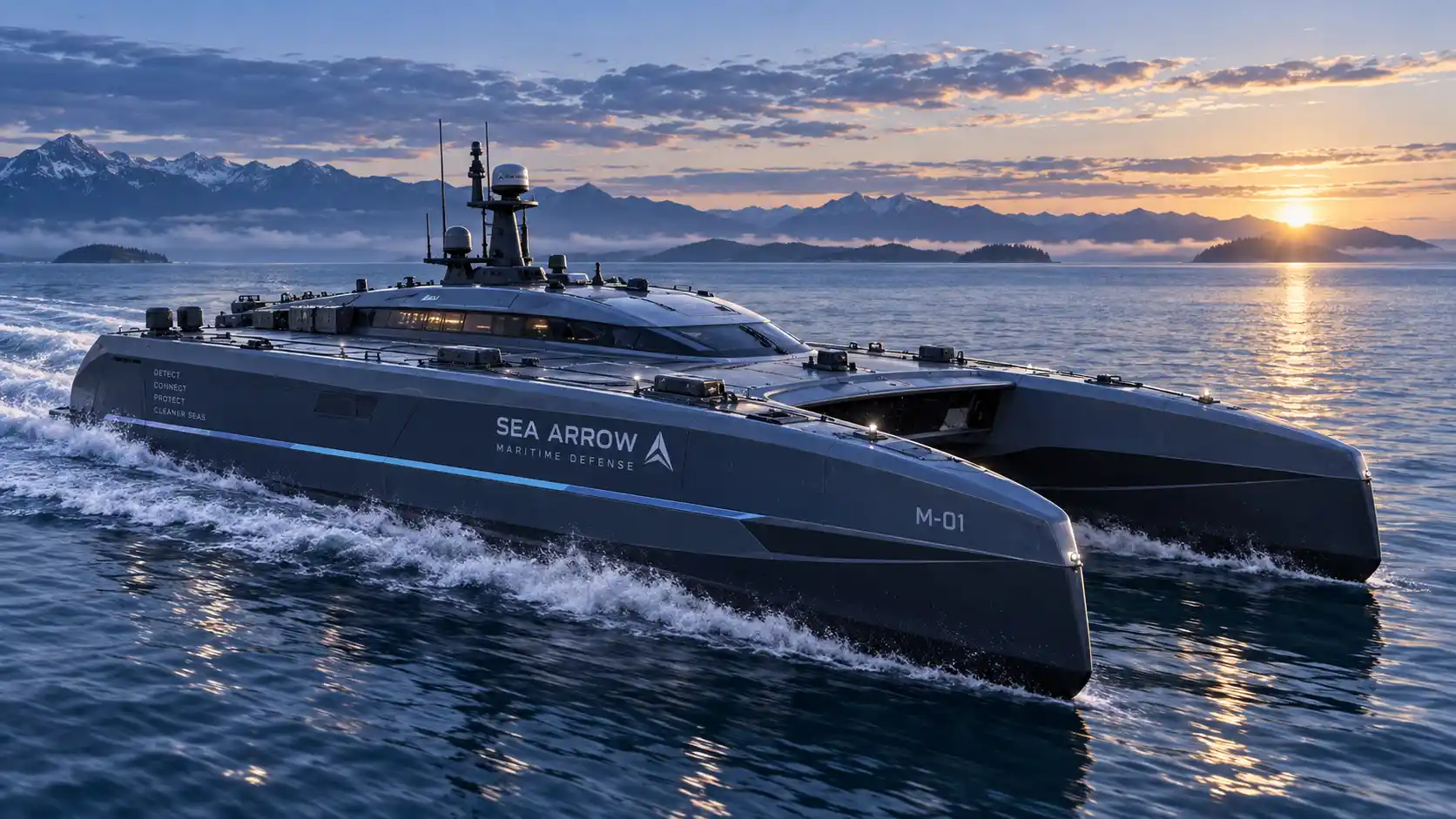
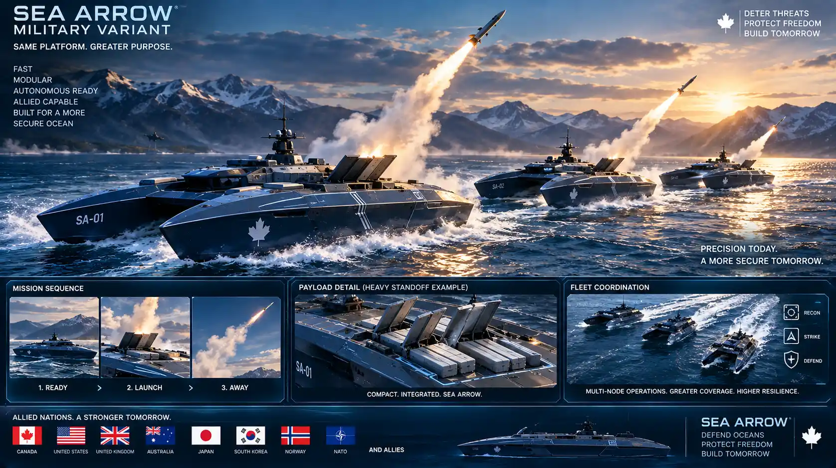
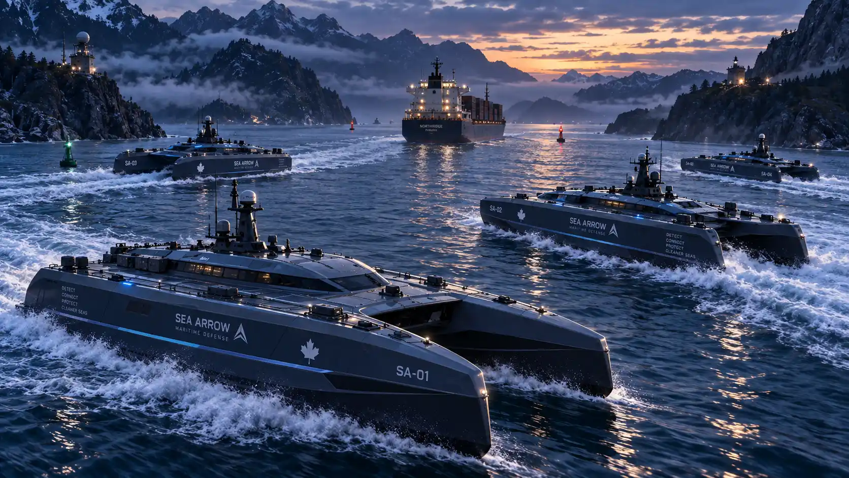
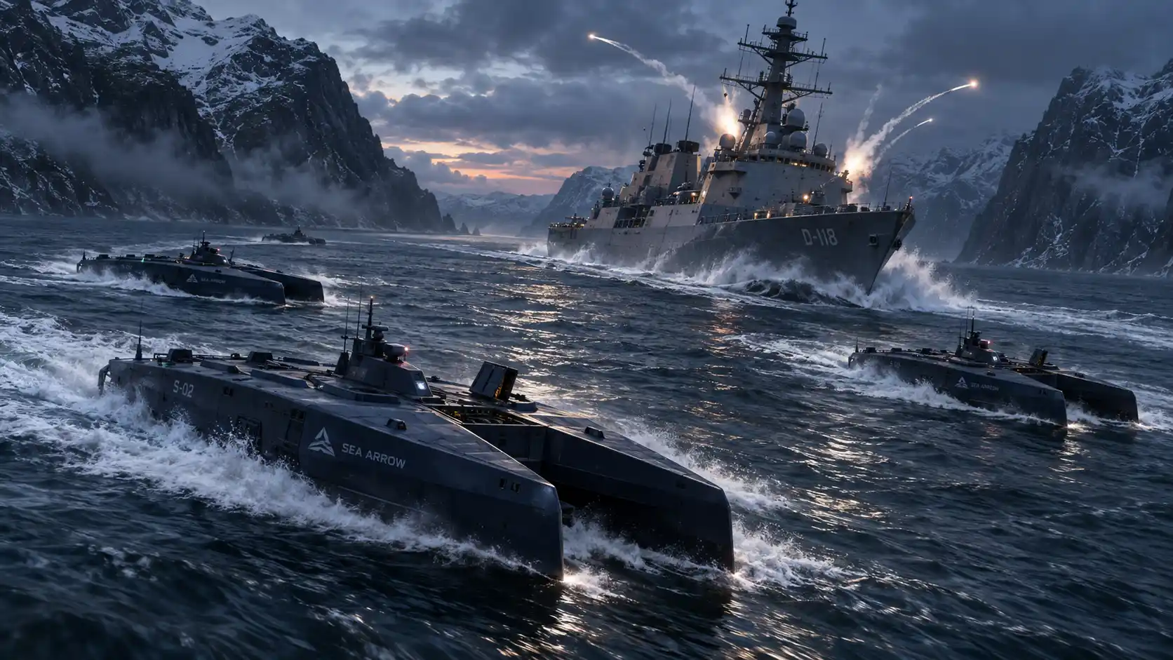
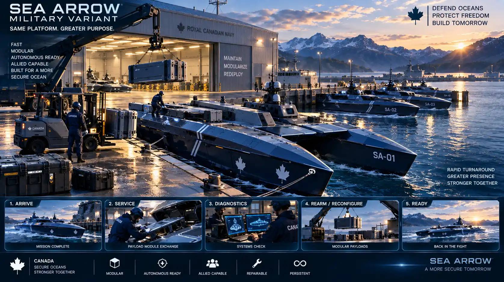
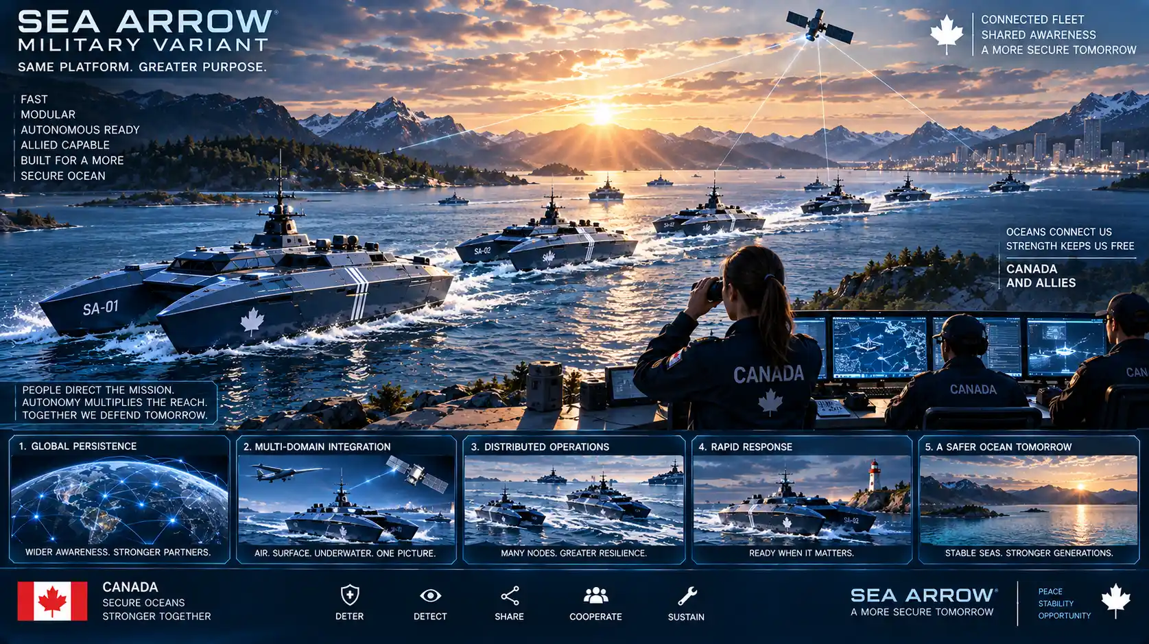
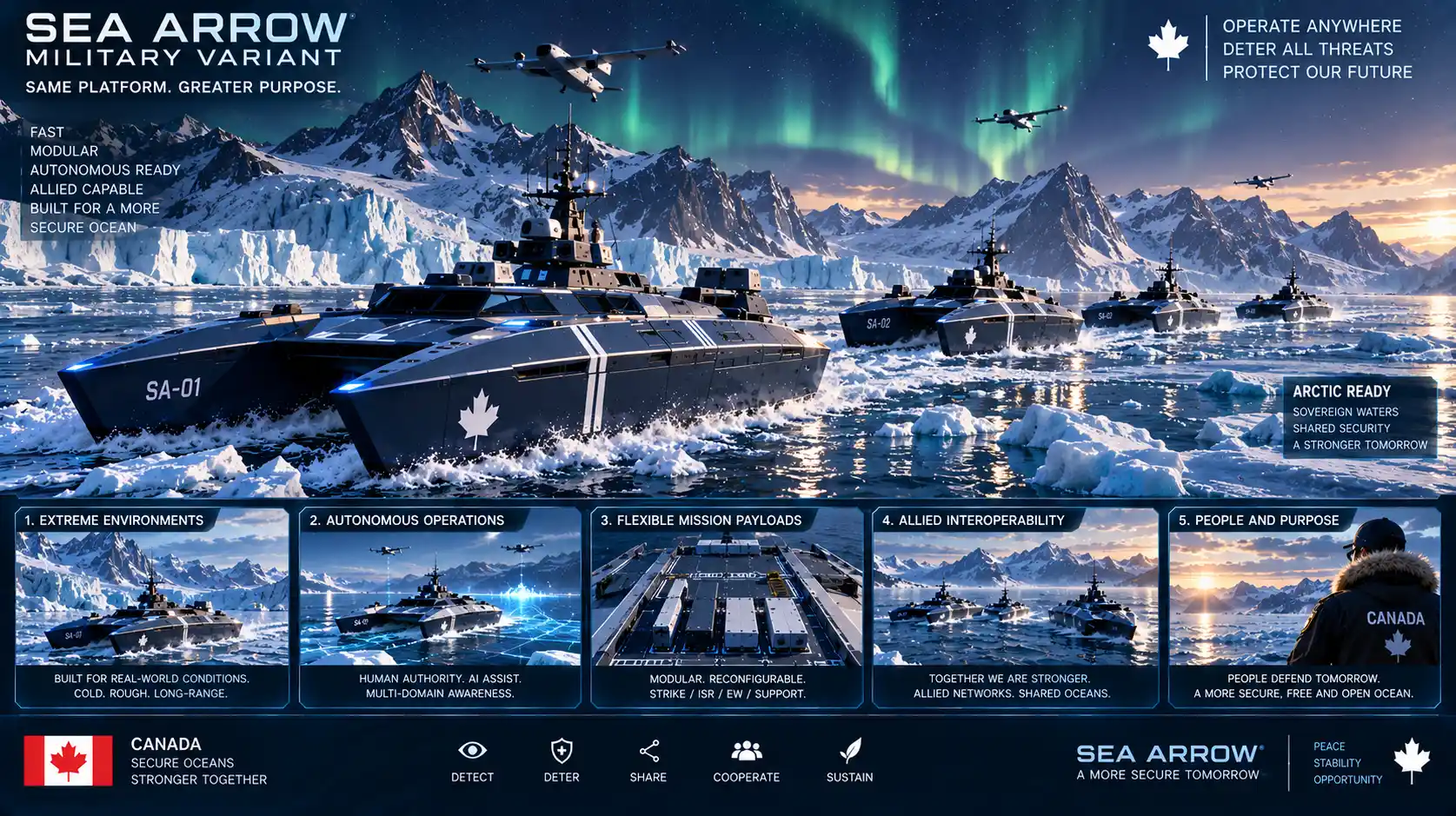
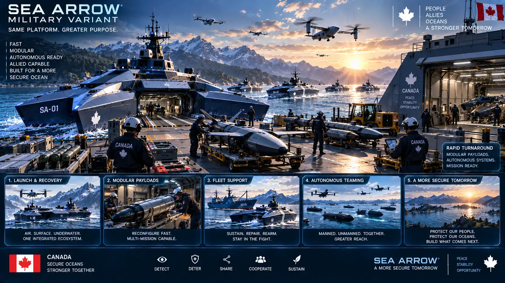
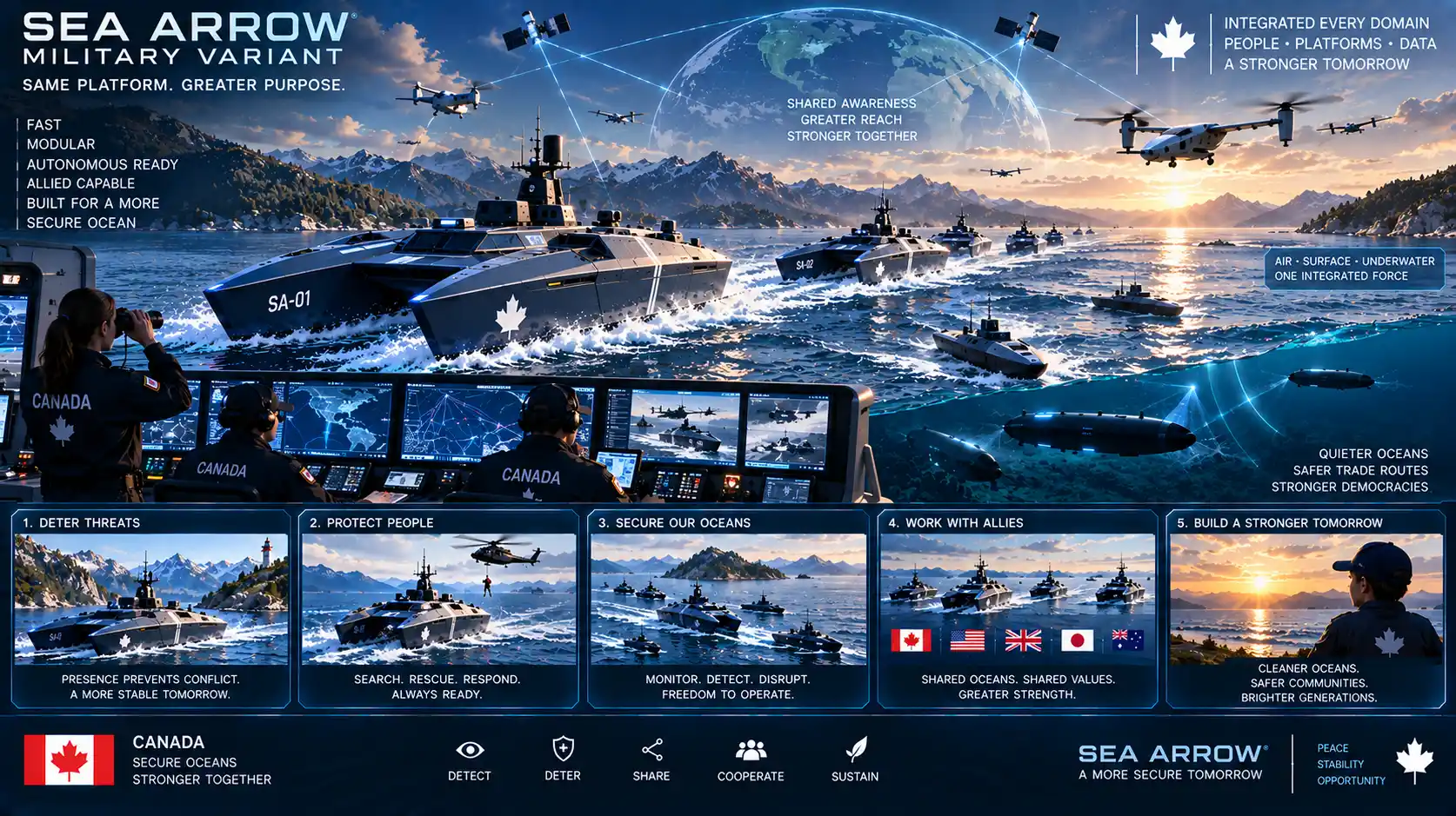
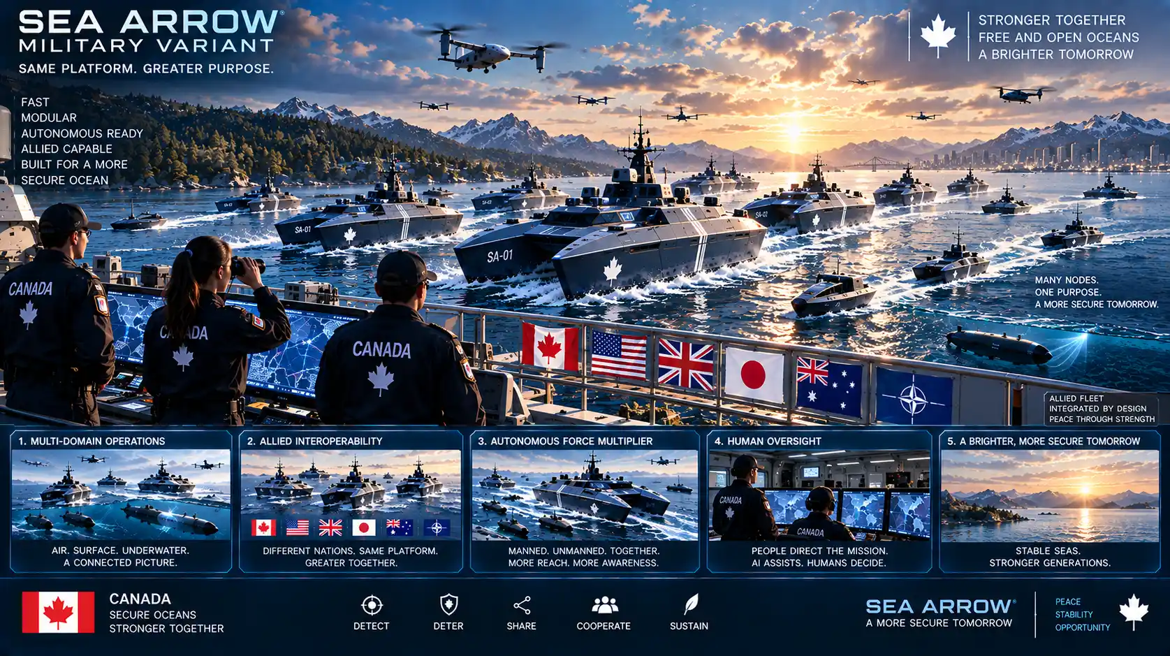
HMCS Prometheus / USS Prometheus – Arsenal Config.